Gehn’s Holographic Imager/Andotrope
For my secret project for Mysterium 2023, I’ve spent the past 8 months making a replica of one of Gehn’s holographic Imagers from the game Riven: The Sequel to Myst… And thanks to some patent-pending new tech I’ve developed that I’m calling an Andotrope, I’m excited to say that the “holographic” part actually functions!


Here’s the contraption in action with zero video editing, CGI or other trickery:
(YouTube link in case the above embedded video doesn’t work for you)
And here’s what the original looks like in-game:


(YouTube link in case the above embedded video doesn’t work for you)
There’s no CGI or video editing in the above video, it’s straight off my phone. There’s also no head-tracking cameras or special glasses or other tricks involved. Unlike the game version, the same image is visible no matter where you stand around it, and this works for unlimited simultaneous viewers. A whole crowd can stand around it and everyone will see not only the same image of a person, they’ll see that person making direct eye contact with them. This is actually far more useful than if it was just a floating head in space like in the game, where 3/4 people get a bad view as they’re looking at the back or sides of the head. It’s full-colour and full-HD.
How it works: the Andotrope
Readers are probably most interested in the Andotrope, which is the main mechanism in the middle that creates the omnidirectional holographic display. It consists of two specially-chosen tablets sandwiched back-to-back inside a black cylinder with viewing slits in front of the tablets, and the whole cylinder rotates at high speed (up to 1200RPM for mine, which gives an effective 40fps). Both tablets synchronise their output, effectively doubling the frame-rate by displaying two images per rotation.
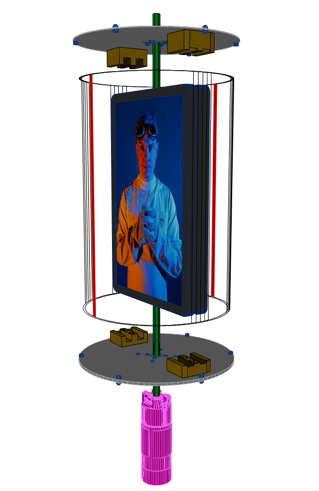
Andotrope exploded diagram. As the mechanism rotates, your view through the red slits sweeps across the displays, which ensures everyone in all directions ends up with a view of the full screen.

Andotrope with the external black cylinder removed, showing the internal components.
The effect is similar to a Zoetrope. Basically, I’ve brought a 150-year-old children’s toy into the 21st century. Because this doesn’t quite meet the definition of a Zoetrope any more, and because I couldn’t find anyone else who successfully pulled this off before, I’m calling any display you could build that’s similar to this by the generic term Andotrope. Here are the key differences between an Andotrope and a Zoetrope:
- An Andotrope uses relatively few screens and can show infinitely-long animations, while a Zoetrope uses a dozen or more still pictures and is limited to showing only a second or so of looping animation.
- An Andotrope’s screens & slits are arranged so that you don’t see multiple animations at once, while in a Zoetrope you can usually see through multiple slits to see multiple animations at a time.
- Because it uses fewer screens & slits, an Andotrope rotates much faster to maintain an animation, rotating tens of times per second, while a Zoetrope might rotate only once per second.
- All combined, the main purpose of an Andotrope is to provide an omnidirectional, bill-boarding holographic* video to multiple simultaneous viewers in all directions.
It’s not an exaggeration to say I couldn’t find any other examples of people successfully pulling this off before; I searched to the literal last page in Google Image Search for terms like “Zoetrope LCD”, “spinning LCD”, “tube POV display”, “cylindrical POV LCD” etc and turned up nothing. Because of this, I’m happy to announce that this display tech is now covered under Patent Application 63/511,582!
It seems I’ve accidentally invented new technology in my quest to make a video game prop more screen-accurate. Um. Oops?
This kind of display has a wide range of applications. I’m going to get a little promotional here but imagine being in a boardroom meeting video call and the boss is in the centre of the table, so everyone sees a clear view of them. Imagine a restaurant table with this in the middle, a digital assistant taking your orders, playing games with you until your food arrives. Imagine this on your kitchen island table showing the weather, currently playing music & other information from your Virtual Assistant, viewable no matter where you’re standing. Imagine those cylindrical advertising posters/screens, but everyone all around always sees the intended view. Imagine theme parks with these futuristic displays around the place. Imagine board games with friends, with this in the middle of the table, the dungeon master talking & pointing to YOU. Anywhere people are in a group where you currently look at a display to one side, this puts the display in the middle of the group. It’s effective. It’s practical. It’s achievable. And it’s relatively cheap.
If your company is interested in commercialising or integrating this tech into your systems, contact me to arrange licensing (obviously just the Andotrope part, not the video game replica parts like the brass cage or base).
(YouTube link in case the above embedded video doesn’t work for you)
There’s lots of fine-tuning to make the visual effect actually work, and selecting the right displays is crucial. I used the Blackvue Tab 10 as it was a good compromise of all requirements. Most important is that the displays must have almost zero flicker since any flicker becomes visible at high speeds, which unfortunately rules out most OLED and a lot of LCD screens that either purposefully flicker the pixels/backlight at a high frequency for dimming or their driving circuitry has a slight voltage ripple that’ll show up. You also want the brightest displays you can get, as a thinner viewing slit means a crisper but darker image – a 5-degree viewing slit means you only see 1/36th the display’s original brightness. Picking displays that are as light as possible makes balancing them easier, and as thin as possible is good for reducing the distortion curve in the final video. Finally, they need to be rugged enough to survive what’s effectively the speeds of a washing machine spin cycle; this is an occasion where devices with poor repairability that have been fully glued shut can sometimes be preferable.

The Andotrope display without the Imager’s brass cage, demonstrating that the final display you see is actually curved. The video is Catherine’s Escape from Riven.
To get the best contrast ratio possible, the outside of the cylinder is coated in Musou Black VL fabric as a compromise to find the blackest black that will hold up to the centripetal forces. My experiments with paints revealed that they didn’t like to stay attached to acrylic spun at high speeds, and the famed “Black 3.0” paint isn’t actually as dark as this fabric. The viewing slits were covered in a layer of 3M anti-reflective film.

Multiple layers of Black 3.0 paint on a Toy DeLorean’s bonnet vs Musou Black VL fabric under a bright light. The fabric is noticeably darker than the paint.
How it’s built: the Imager’s brass cage
The whole imager is actually only 60% scale of the original in-game one, because the original was just impractically large and everyone who has seen it in-person (including the game’s creators) thinks my one is the right size & big enough. The spherical cage is constructed of around 12 metres (40 ft) of 6 mm brass tube. The 20 segments were professionally bent, cut to length, filled with resin to provide extra strength (don’t forget these tubes hold the top of the Andotrope in place, meaning they’re structural), and a hole drilled through each end. They’re secured at the top & bottom by a bolt going through that hole, through a 3D-printed holder, to a Stainless Steel plate. There’s a matching second 3D-printed holder that goes on the inside of the cage, sandwiching the tube in place between both holders. The penta-bolts squeeze both 3D-printed holders together, firmly gripping all the tubes.
I applied a clear coat to the most of the brass to preserve its shiny appearance, while leaving the cage tubes untreated to allow them to develop a natural tarnish over time. Here’s what the inside of the mounting points look like to give you a sense of how complicated they are & how fiddly it was to assemble this in the limited space.


3D-printed components
I divided the 3D-printed holders into 5 segments, because I held true to the spirit of Riven/Gehn to that level of detail. Modelling them presented challenges such as matching the curves of the tubes, ensuring proper clearance for bolt heads and access for tightening bolts, optimising the design to minimize resin usage, and incorporating drainage holes for improved printing. All of which is millimetres (or sometimes under a millimetre) away from one another. They represent the most densely complicated parts I’ve modeled and printed to date. They’re super pretty though.


I designed four 3D-printed grips that securely hold the tablets in place and can be adjusted to balance the device. These were honeycomb-hollowed not only to save resin but also save a few grams of weight since they are part of the rotating mechanism. Including the spherical dome on top, this makes the total number of resin 3D-printed parts… 25. Gehn’s extra favourite number. Mwahaha.


The base case was FDM 3D-printed in 4 parts out of PLA+, a corn-based plastic. Modelling & optimisation took around 30+ hours for these parts, with an additional approximately 70 hours for printing. The quarters were bolted together then covered in flexible automotive putty and painted up to resemble rock. The interior was coated in noise & vibration-absorbing paint to help make moving parts as quiet as possible.


The Imager’s base
The Imager itself stands as its own work of art. I wanted it to be as authentic to the game as possible, so metal was used for a lot of the internal and external components. 3D printing, laser cutting, resin casting etc all have their places (and all were used to create this device in other areas) but none match the aesthetic appeal of actual brass. The long-necked three-way toggle switches on the front are all made of stainless steel, while the brass panel they’re attached to serves as both the access panel for the internal electronics and features an exciter on its back, so the entire panel functions as an invisible speaker. The Imager’s handle is made from machined stainless steel, mounted on a cast iron crank, connected to a brass axle, which in turn is attached to a dynamo designed for wind turbines. As a result, you can feel the weight and resistance of real metal in your hand, while it actually generates electricity and produces the right kind of whirring sound, resembling a proper machine rather than a plastic toy. Since human output is too intermittent to reliably power the device, I incorporated a power cable made of mains-rated braided twisted jute, to maintain consistency with the overall design aesthetic.


Altogether, the Imager weighs 13 kg (29 lbs), stands 71 cm (28 in) tall, and utilises over 300 bolts. Speaking of bolts, yes, those are 5-sided pentagonal bolts, or “pentabolts”. Just like Gehn used in the game. And every single one serves a structural purpose; none are merely decorative additions. I meticulously sanded off the stock markings from each bolt to maintain the 90s-basic-3D-model-shape aesthetic without any distractions. I sourced mine from McMaster-Carr.


I have to share these 3D wireframe views even though I know it’s a bit hard to see anything in them because they illustrate well the amount of complexity inside the machine. Plus, the top-down view looks a bit like an Iron-Man-style Arc Reactor. And when you’re creating things that accidentally resemble Iron Man’s equipment, that’s a sign you’re on the right track.


Internally, things are built from a mix of Aluminium to save weight, Stainless Steel where more strength is needed, pure steel for the device’s main axle, and brass where it would be visible (always the thinnest sheet I could get away with to save weight & reduce costs). The main internal structure is constructed using T-slot, opting for their slightly higher strength compared to V-slot. The mechanics come from goBILDA, a company that specialises in robotics competitions, but they’re also great for quick prototyping with all their components using a well-thought-out modular grid system. I strategically placed rubber washers and rubber sheets throughout the device to minimise machine noise & vibration. My cat Lana supervised the assembly process, because the Internet insists that all decent build logs should include at least one picture of a cat.


Electronics
Due to the intermittent nature of a human turning the crank/dynamo, the imager is powered by a Meanwell 12V power supply that accommodates both 110V & 230V. The motor driver is a DFRobot DRI0042, with an Arduino Pro Mini acting as the motor controller. A Raspberry Pi 4 with an attached DAC+ shield for audio output serves as the heart of the machine that controls all the other components. To prevent voltage spikes or reverse current from motor braking, a Pololu Shunt Regulator is used to keep the voltage below 13.2V.
. From left to right: 12V Meanwell power supply, Pololu Shunt Regulator, Raspberry Pi 4 with DAC+ shield, Arduino Pro Mini, DFRobot DRI0042 Motor Driver.")
The electronics inside Gehn’s Imager that drive the Andotrope display (only some of the wires are connected in this photo). From left to right: 12V Meanwell power supply, Pololu Shunt Regulator, Raspberry Pi 4 with DAC+ shield, Arduino Pro Mini, DFRobot DRI0042 Motor Driver.
Although the game version of the Imager doesn’t have them, I added five three-way toggle switches and a brass panel to control it. The first switch controls the power. The second switch controls the speed, with settings of roughly 20fps, 30fps or 40fps. Slower speeds produce quieter operation, while faster speeds result in a more stable image. The third switch adjusts the volume. The third, fourth and fifth switches are for video selection, offering a total of 27 available videos. Speed and volume adjustments can be made at any point during the Imager’s operation.
One significant aspect to making the Andotrope work is that all communication between the Raspberry Pi and the tablets occurs over Wi-Fi. Physical wired connections, such as brushes or slip rings, aren’t reliable for high-bandwidth data connections, and I know some have said that Wi-Fi can become unreliable at high speeds, but I haven’t noticed any issues in this application. MQTT handles the basic communication, and optimisations have been made to minimise latency so the tablets stay synchronised. For example, dummy packets are sent every 8 seconds to prevent the Wi-Fi chips from entering low-power mode. And because all communication happens via Wi-Fi, I can also control every aspect of this Imager from my phone – including playing back extra videos that aren’t on the switches.
I wrote a custom app for the tablets to handle network communications & play videos (though you can also run any other app to watch something on YouTube, video chat, play a game, etc). The tablets’ backlights dim in between videos to conserve battery life and maintain a visually seamless black appearance of the cylinder. This also means the tablets’ batteries last a full day between charges.
The Dabber
In case I ever need to manually use the tablets due to a pop-up menu or something, my other half created this neat little device we named “the dabber”. It’s made out of hand-carved leather & thread with a wooden handle. A conductive stylus tip is attached to the end, with enamelled copper wrapped around it down to the handle to give it sufficient capacitance. It fits through a small hole in the top of the cylinders, and when you rotate the spindle on the handle, it bends over in that direction. Removing the tablets from the brass cage requires significant disassembly, but this plus the small amount of space you get by lifting the end cap off the cylinder is enough access. If a lot of tapping is needed, a Bluetooth mouse does the job.

The Dabber. A custom tool made of wood, hand-carved leather & thread designed so you can use the tablets inside the Andotrope/Imager without removing them.


(YouTube link in case the above embedded video doesn’t work for you)
Presentation
Below is a video of my Mysterium 2023 presentation, and here’s a copy of my slides.
(YouTube link in case the above embedded video doesn’t work for you)
Improvements
There’s lots of ways you can iterate on the Andotrope design, some of these I intended to implement but I ran out of time before the presentation. I’m sure some people interested in licensing this tech will be interested in developing some of these ideas further. Here’s a few of them:
- Wireless power, eliminating the need for manually recharging the tablets. I bought the coils for this but I didn’t have enough time to wire them in.
- Anaglyph/Red-Blue Glasses 3D. Right now, this is just a matter of playing a correctly-formatted video.
- Polarised Glasses 3D by using different polarising filters on each tablet. I had planned to implement this feature, but once again, I ran out of time.
- Different numbers of screens. I used two screens as they conveniently balance themselves and give you twice the brightness, but there’s no reason there couldn’t be 1, or 3, or even 5. Higher numbers increase cost & complexity but provide a brighter image with reduced spinning speed for the same equivalent frames per second.
- Different sizes are definitely possible, from a small cheap phone-sized Andotrope to a larger monitor-sized screen. The main limit for larger sizes is overcoming centripetal forces. A cost-effective “BYO device” version could also be developed for different sized phones/tablets.
- By carefully synchronising the timing, frames could be synchronised across screens so each one always shows a different frame vs showing identical frames. When streaming content to two screens via Wi-Fi, this could reduce the amount of data sent by half.
- Using displays with very high frame rates and carefully synchronising timing, you could present different images to different directions simultaneously. Then you really could show some viewers the sides and back of someone’s head.
- Alternative screen technologies can also be used. OLED would be awesome if it didn’t flicker, particularly a flexible OLED that you curve so the final image appears flat. I investigated both transflective and e-ink tablets for this device, as you could front-light those with very bright LEDs, but all currently available options had poor contrast ratios.
- The enclosure doesn’t necessarily have to be solid. You could use something like privacy film, shuttered lenses, or other techniques to make sure the light from the screen only goes in the direction of the viewing slit, and the rest of the enclosure could be open. Make a significant portion of the enclosure open would result in a partially transparent display. I really wanted to do this but just couldn’t manage it in the limited time I had. There’s no reason the enclosure has to be a cylinder, either.
- Positioning optics either in front of the tablet or at the viewing slit to better direct the screen’s light. This would increase the display’s effective brightness, and it could also be used to reduce display distortion.
Addendum: other videos, assembly photos
Below are additional videos of other content currently loaded onto the Imager.
The original Andotrope proof of concept – a rugged phone, inside a tomato soup can painted black & sliced open, hot-glued to a pedestal fan. Hacky as all heck, but it proved the concept works.
Riven: Gehn’s Schoolroom Imager original in-game video. Compare it with my remade version.
Riven: Gehn’s Schoolroom original video, this time played on the Andotrope.
Hatsune Miku – World is Mine, because of course I had to. This is an earlier video from before I fine-tuned the synchronisation code.
Imager Explanation Instructions. This plays if you flip all switches up.
Riven: Moiety Sickle. This is exclusive new content from the remake of Riven, not the original. This is an earlier video from before I fine-tuned the synchronisation code.
Cyan Intro Logo.
Riven: Gehn’s Age 233 Office Imager of Keta: Original In-Game Video.
Riven: Gehn’s Age 233 Office Imager of Keta: Played on the Andotrope.
Riven: Minecart Ride. This is an earlier video from before I fine-tuned the synchronisation code; you can see a smoother version of this during my presentation.
Riven: Mag-Lev Ride. This is an earlier video from before I fine-tuned the synchronisation code.
Star Wars Episode IV: A New Hope Death Star Trench Run animation.
Riven: Catherine’s Freedom. This is an earlier video from before I fine-tuned the synchronisation code.
Myst IV: Intro video.
Myst IV: Atrus’s Intro Speech.
Myst 3: Amateria Ball Ride.
Obduction Mayor Introduction video. This is my personal favourite.
Firmament Trailer. This one does a good job of showing the maximum size a video can be.
Riven: Gehn’s Opera Easter Egg. Because I couldn’t resist being silly.
Gehn: “I apologise for the cage” (except I really don’t).
Riven Remake Teaser Trailer.
Mind Blown Meme Guy.
Mr Burns Computer Greeting.
Cool-looking Exploding Particles.
A Cat. The internet demands it.
Generic 3D Animal Imagery.
Here’s a few action shots of the assembly process.

Partially-assembled selfie!

Assembling the imager.

Assembly yoga.
Finally, if you like the Andotrope technology at the heart of this video game prop replica, you should check out my version 2 Andotrope proof of concept. It’s smaller, faster, quieter and cheaper – aka better in so many ways!
Similar Posts

Gradientment, the Image Gradient Map Generator
Gradientment converts your 2D images into two overlapping 1D gradients & spits out the highly-compacted CSS used to generate these gradient maps, for perceived-faster progressive image loading or for artistic purposes. Sure, you could use...
New Andotrope Website
This is just a quick update to say that I’ve launched a new website for my Andotrope omnidirectional displays! Having a dedicated space to promote them makes it easier to share them with others. Plus,...
Utterly brilliant.
You have reacted quite – er – strongly to suggestions that your device is not holographic.
Can you please explain in what way your device *is* holographic? I as as one who has done some work with holographic optical elements and held a patent in the field.
It’s amazing. I would love to know your patent process as well. How much did it cost you?
Awesome 😎. I am going to assign this article to my engineering students as required reading.
Shut up and take my money!!!
First and foremost, this is just /stunning/. I am at a loss for words with how this sits at the intersection of new technology & adherence to the source material with regards to the bolts, and common incorporation of ‘fives’.
As an improvement, I am reminded of the similar engineering problem of rapidly seeking a laser, which was solved by introducing a mirror between the laser and the target, then moving the laser. I wonder if there is some optical means of projecting the image onto a lighter weight and technologically ‘simpler’ mirror. I know that without rotating the image in the base then it will rotate as the device spins, but I feel like there is a clever optical solution that hasn’t yet been considered (fiber optic slip ring? 😏) that might ease construction.
I would love to have this in the centre of a meeting table so we can all look at the same digital view of something we are working on together in a meeting, while also being able to look at each other to make eye contact, talk, and feel connected. Kinda like physical screen sharing, but not all staring at the screen on the wall.
Using a 3rd display and perhaps at higher refresh rates, I’m sure you could make something with even more effective visuals and 3D effects.
I absolutely love this!
Quick math question though, how did you arrive at the calculations to convert the RPM’s to FPS?
Simple answer – just divide RPM by 30.
Longer answer – convert Revolutions Per Minute to Revolutions Per Second by dividing by 60, then multiply by 2 because there’s 2 images shown per revolution.
Found a 2016 patent for a similar device – TWM541016U
I also found a similar patent, from 2003: US20060179693A1, “Device providing simultaneous visibility of images within the area of 360 around itself”
You should look at the work that Robert Collender did in the early 1960’s. He called his device a Stereoptiplexer. Check out US patents 3178720, 3324760, and 3815979. They are most similar to this. You can also look up some later patents of his that essentially turned things inside out and projected out onto a static curved screen. He also wrote about these in articles in the SPIE and Information Display.
Please check patent JP6191001B2, which describes a similar invention.
In all seriousness, I am exploring the potential integration of this technology with an AI agent personal assistant model I am developing. My primary focus is on NDIS participants and mentally ill individuals let down by the system. I feel participants would benefit significantly more from your “face to speak to”beyond my current STT-TTS capabilities. I believe that the personalisation factor would be highly beneficial in addressing numerous conditions and improving participants responses to the system overall. If you have any way to contact me to discuss this further, I would be eternally grateful.
Hi Ando
I attempted to replicate PaulDeBevecs 3d projector.
Failed as I could not get the refresh rate to work.
Anyway, I operate a multi camera array for the film industry and about to retire.
But it would be nice to explore 3d applications of your invention
I’m in Melbourne if you would like to catch up
Hi Mark!
3D is possible a few ways with this technique; the easiest is to lock the rotation speed to a multiple of the devices’ screen’s framerate, use devices with screens with a high framerate, present different images to different directions, and quickly cycle between the images. I’ve tried it out and it looks pretty neat, and definitely has its applications. I personally prefer it with just one image displayed in all directions (viewing someone’s face is much more interesting than viewing the back/side of their head), but it would depend on what you want to do with it.
I’m not sure when I’m next going to be down in Melbourne, but if you’re ever up here in QLD, drop me a line and I’d happily give another industry professional a demonstration! It looks so much better in person.