On the 7th of November 2020, Cyan Worlds announced the first annual Myst Island Cake Baking Contest, under the #MystIslandCake hashtag. I couldn’t resist having a go… Around 60 hours of work between us later, here’s the end result!
We started with planing the design – specifically, how could we make a unique approach to this cake, so it wasn’t just another iteration of Myst island. That’s when I had the idea to show a cross-section of the island to display the subterranean caverns. Meka loved this idea, and with his background in architecture, he was well equipped to visualise the final product.
As a way to take stock of what ingredients are available to make this edible diorama, we took a few trips to different stores to find the best ingredients for sculpting and cake decorating. The grocery store had a decent selection that would have been fine, but the trip to a specialist cake decorating shop had fantastic things such as bronze food paint & powdered food colouring.
The making process begun with choosing an appropriate scale to make the cake. Using a 3D model of Myst Island, we found a size that would allow Meka to sculpt the smallest models we wanted to include, as well as considering how much fruit cake we can realistically eat (side note: this is Australian-style fruit cake, which is far more edible & tastes far better than its international counterpart). The board is around 600mm by 300mm, or around 2′ by 1′. I then printed out scaled drawings of the plan view of the island for Meka to start sculpting. Being able to consult these wireframe images, as well as measure dimensions straight off the 3D model, was super handy to make sure everything was scaled correctly & in the right place. Sculpting all the individual buildings, trees & artefacts took many days of fiddly work until we had the majority of the chocolate and sugar cake toppers finished.
2 days put from the deadline, the cake sculpting began. A copy of the island plan was made on baking paper, which was used to make approximate placement of the landscape, contours, buildings & the dock. Again I was in charge of scaling the elevations of the landscape, while Meka’s sticky but far steadier hands sliced away at the cake.
Once we were happy with the overall shape of the island (taking into consideration the underwater portion of the island that Meka approximated), the cake was generously drenched in rum so that it would stay preserved for weeks. There was also the added bonus that the rum helped pull the crumbling cake together after much cutting & piecing together.
It was now time to put on some top soil. A thin layer of brown fondant was stretched across the fruitcake & massaged into shape. The rock portions of the island were painted with a palate of royal icing in different colours to approximate granite, and a layer of moulding chocolate put on the cake board, ready for the ocean water (a mistake we would soon find out) The tricky job of making the sectional view of the internal chambers took a little planing & creative licence. As many Myst fans may know, the chambers don’t exactly fit in the island faithfully, and to make a clean section, a small amount of artistic license was required.
Grass made of crushed digestive biscuits mixed with shredded coconut was applied to the appropriate areas. The buildings, pathways, stairs, ships, pillars & trees were positioned and blended into the landscape, before a dam of packing tape & cardboard was constructed around the cake ready for the sea water. The ocean water was made with agar powder, water, sugar & flavouring, which was cooled to 40’C/105’F before being poured around the cake. The underwater chocolate & the fondant of the island began to dissolve in the agar, even though the jelly was hard. This was not a major problem as the colour stayed in the jelly, and the dissolving fondant dripped slowly, which we continued to mop up.
After removing the jelly mould, the cake was almost done, but there was a blank space on the side where the island was cut off. Meka had a plan for this – literally! He drew out the plan view of the island, as though Atrus was still in the process of writing the island into existence. It was finished with a chocolate version of Atrus’s quill and ink, along with his memorable words.
Aside from some small amounts of armature wire to hold up things like the trees, everything else in this cake is edible. Most importantly, most of the sculptures are chocolate-based instead of being fondant-based, so it actually tastes good too (eg the quill is entirely white chocolate). And now that it’s finally done, it’s time for us to enjoy some cake after staring at it all week! *nom*
There’s a running joke amongst my friends that I’m an actual time-travelling mad scientist – mostly because it’s more true than false. So I figured, why not run with it a little and have some fun with it. So that’s what I’ve done here – I’ve restored this old Mad Scientist’s Knife Switch into perfect working order!
A 2x DPDT knife switch, rated for 500V 60A, with arc suppressors
Just cleaning it & replacing the springs was the easy part. Safety is important – especially when you’re going to have “exposed” bare copper like I have here. For this knife switch the exposed bare copper is only ever running at 5 Volts, and those +5V connections are used to open/close some relays, with additional protection if the exposed areas ever go too high in voltage or current. You could lick the bare copper if you wanted without feeling so much as a tingle. But I don’t recommend licking copper; it tastes bad.
Fully restored/repaired/running, this knife switch is now sitting around my house as a random extension cord you can use to turn on/off any appliance it’s paired with. Because why not make turning on a lamp a little bit more Mad Sciencey.
My DeLorean‘s now 39 years old, which means it’s got a long list of “nice to haves” that aren’t critical but they either need some attention or outright replacing. One example is the foam in the door trim panel upholstery – it collapsed into a black powder a long time ago, leaving the door interiors completely flat, hard, and devoid of depth or shape. So let’s fix that! DeLorean Go offers a Door Card Foam Repair Kit that provides all the necessary materials. As I’m in Australia with international shipping restrictions on certain chemicals, I opted for the kit with 2 tubes of glue instead of the tin of glue. Personally, I would’ve found it better to use 3 tubes of glue, and I recommend you buy 3 tubes just in case. However, you can definitely make do with just 2 tubes. You could probably DIY this at a lower cost by finding suitable foam in the 1/4″ or 6-8mm thickness range. However, I’m unsure about the best density/firmness and the right foam material. So for this job, I’m sticking with the vendor-provided option, which also supports the vendors.
DeLorean Door Upholstery Padding Before
As far as jobs go, this one is more fiddly than tricky. There’s a trick to popping the door trim panels out – have your window down while you do it, and use an upholstery fork/fir tree/trim removal tool to pop the fir tree fasteners one at a time. You can use a screwdriver if you must, but I highly recommend even a cheap plastic trim/fir tree removal tool to save time. Carefully peel the vinyl off your fibreglass/plastic inner door frame. The dust from the old disintegrated foam will want to go everywhere; make sure you completely vacuum out the old foam dust from all the pockets otherwise you might accidentally get some on the adhesives and they won’t stick as well. Cut the new foam to size and insert it – the roll I received was enough for around 3 doors, so there’s plenty if you make a mistake. Remember the old advice: it’s easier to make a bigger piece smaller than a smaller piece bigger. The doors are theoretically mirror images, but since these cars were hand-made, there might be a tiny bit of variance between them. When gluing, apply the glue to both surfaces and let it dry a little before pressing them together. It’s also essential to keep the vinyl stretched taut over the backing piece as you work when gluing it on to avoid any bunching or ripples. Finally, this is a great time to replace your door’s fir tree fasteners if your old ones have become mangled over the decades.
The end result should look something like this – the extra curves & shaped definition in the vinyl are subtle, but they’re definitely present and make the doors look that little bit better! I’ve done my best to take both of these photos from the same position and angle with as close to identical natural lighting as possible, making the comparison easier to see. By now, all DeLoreans will have collapsed door foam if hasn’t already been replaced. Whether or not you think this needs doing to your car is entirely up to your personal opinion.
DeLorean Door Upholstery Padding After
Like this article?
Did you find this useful? Donate to my Ko-fi, comment below or drop me a line to say thanks! The more donations/encouragement I receive, the more likely I am to write more articles, guides & tools like this in the future.
My wall clock in my house recently died, and with there being a running joke that I’m a time traveller thanks to my DeLorean, I thought I might as well build a replacement clock myself so it could be extra unique. Here’s what I came up with: a self-setting, self-correcting, self-adjusting wall clock/chronometer that tells time both in our timekeeping system and in the 25-hour D’ni timekeeping system used in the Myst series of video games. This is actually pretty handy if you want to know if it’s the right time to log in for certain events in Myst Online: Uru Live.
It tells you the time both in our “surface” time and in the D’ni cavern!
Technically it’s more a “chronometer” than a “clock” – the main difference between the two is that chronometers have far higher accuracy & precision, to the point that they can be used for scientific experiments. For this one, it’s generally safe to assume it shouldn’t read outside 0.003s of the actual time, but in practice it’s usually under 0.001s of the actual time. It’s no atomic clock, but it’ll do for most of my slow-mo needs. The whole project’s been designed to be as cheap, low-tech, skill-free, and expensive-tool-free as possible.
First up, a little primer – the digits used in the Myst games, aka D’ni digits, are a base-25 numbering system. This means they count up using symbols like [1], [2], [3], [4] … [22], [23], [24], [1][0]. That is, what they call “10”, we call “25” – the same way that in hexadecimal “10” represents what we call “16”. The numbers themselves are based on the numbers 0-4, which are then rotated anticlockwise 90° to represent 5/10/15/20. Here’s an example of D’ni numbers, showing how you add the row & column header symbols together to get the final number symbol:
Each D’ni “day”, or “yahr”, is roughly 30 hours, 14 minutes long and each D’ni “second”, or “prorahn”, is roughly 1.4 seconds. The Guild of Archivists has more details on how the actual D’ni timekeeping system works if that interests you. There’s nothing like these digits anywhere out there on the market, aside from something way over-complex like using LCD displays, but that didn’t interest me much and wouldn’t meet the goals of cheap or low-tech. So I had to come up with my own… And here’s how that turned out!
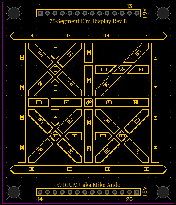
There’s so many places I could start with describing how this project was made so I’m gonna pick the one that probably interests most people reading this – the custom D’ni digit 25-segment displays! These are basically like my own custom 7-segment displays, but they’re easier to read with much higher contrast than store-bought 7-segs. I couldn’t find any instructions or guides out there on how to make your own (I’m sure there has to be some out there somewhere), so I had to work it all out myself from trial and error. The design itself was all made in Inkscape. Laser cutting holes in sheet acrylic and filling them with translucent resin was the way to go. The trickiest part is to have even light diffusion throughout an entire cell. The black parts are made from laser-cut 4.5mm black acrylic.
Laser-cutting D’ni digits out of acrylic
To help bounce light around inside each cell as much as possible, I airbrushed them with a thin white paint before filling them with resin. For the side that was to be the “front”, aka the good-quality side, I wanted the poured resin cells to be smooth & flush with the surface of the acrylic, which is tricky. I placed a piece of clear packing tape on a table with the sticky side up, stretched it out as far as I could, then carefully placed the front of the acrylic piece on the stretched tape. This kept the packing tape under constant tension, so that the resin cured against a smooth flat surface. The empty cells were filled with a 7:1 mixture of clear resin with super fine plaster of paris (mixed before pouring, obviously), which was the best-looking diffusing medium I tried. If you try this, sift the plaster into the resin while stirring to make it as evenly distributed as possible and to reduce plaster clumps in the resin. Use a needle to break up the remaining clumps and to remove any air bubbles that might be stuck in the corners. I recommend carefully picking up the cured acrylic blocks and looking at them from underneath to check for any plaster clumps or bubbles too. A vacuum chamber would be great if you’ve got one to remove the bubbles, but I didn’t have one. Once the resin was cured I carefully removed the packing tape and the segments were ready.
At 4.5mm thick, a single layer of diffusion from this material is likely good enough for most people, but just to make the light segments look extra smooth I used two layers of resin-filled acrylic. However, in this video you can see that there’s a lot of light bleeding from one cell to another, so to seal the edges well, I laser-cut some cardboard gaskets out of 2mm thick black cardboard backing board. I painted the interior edges with a silver pen to increase reflection. I used these gaskets between the two layers of acrylic as well as between the acrylic and the circuit board. I tried adding layers of proper light diffusion film between the gaskets, but they did so little and they would’ve been so fiddly to place in each cell that I didn’t bother.
The 5 layers in the 25-segment digital D’ni display modules – acrylic layers on the left, cardboard gaskets in the middle, circuit board on the right
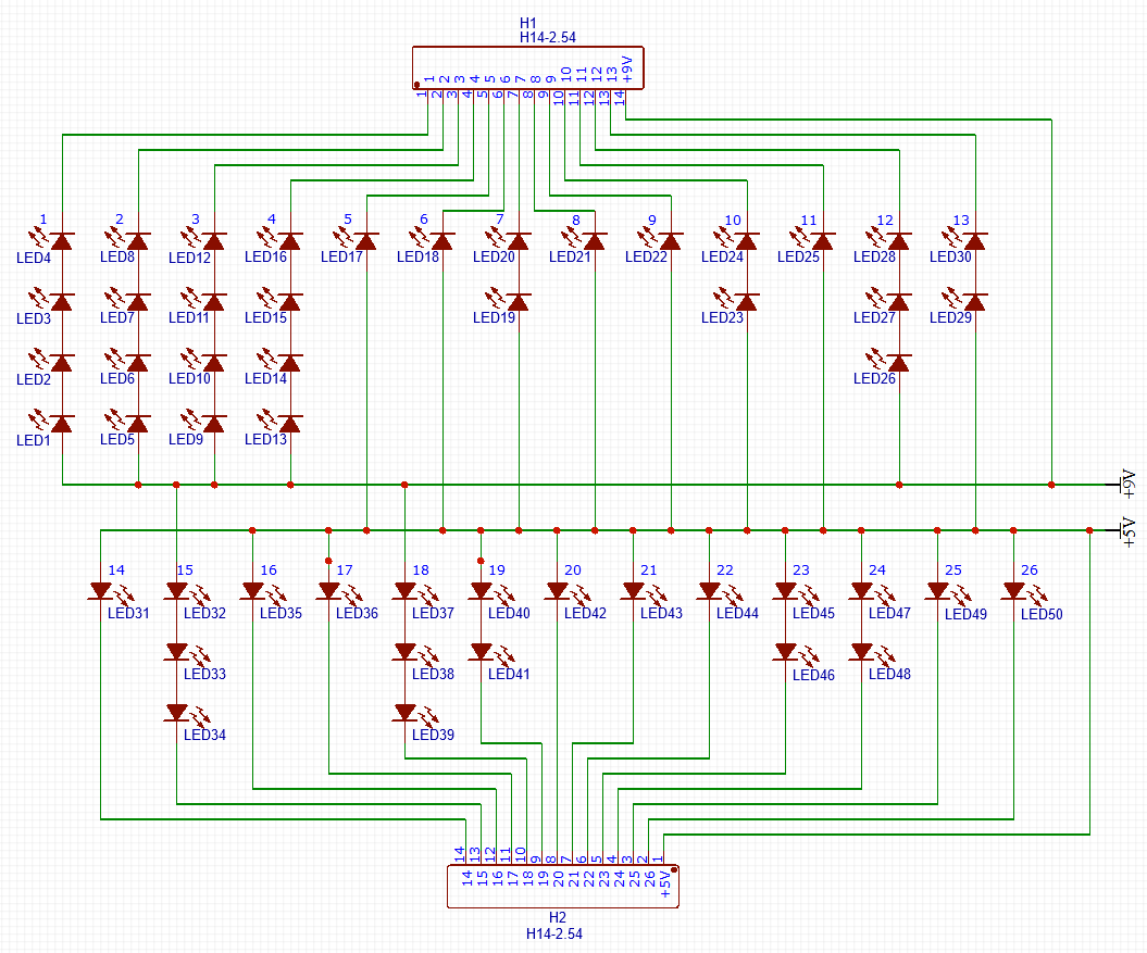
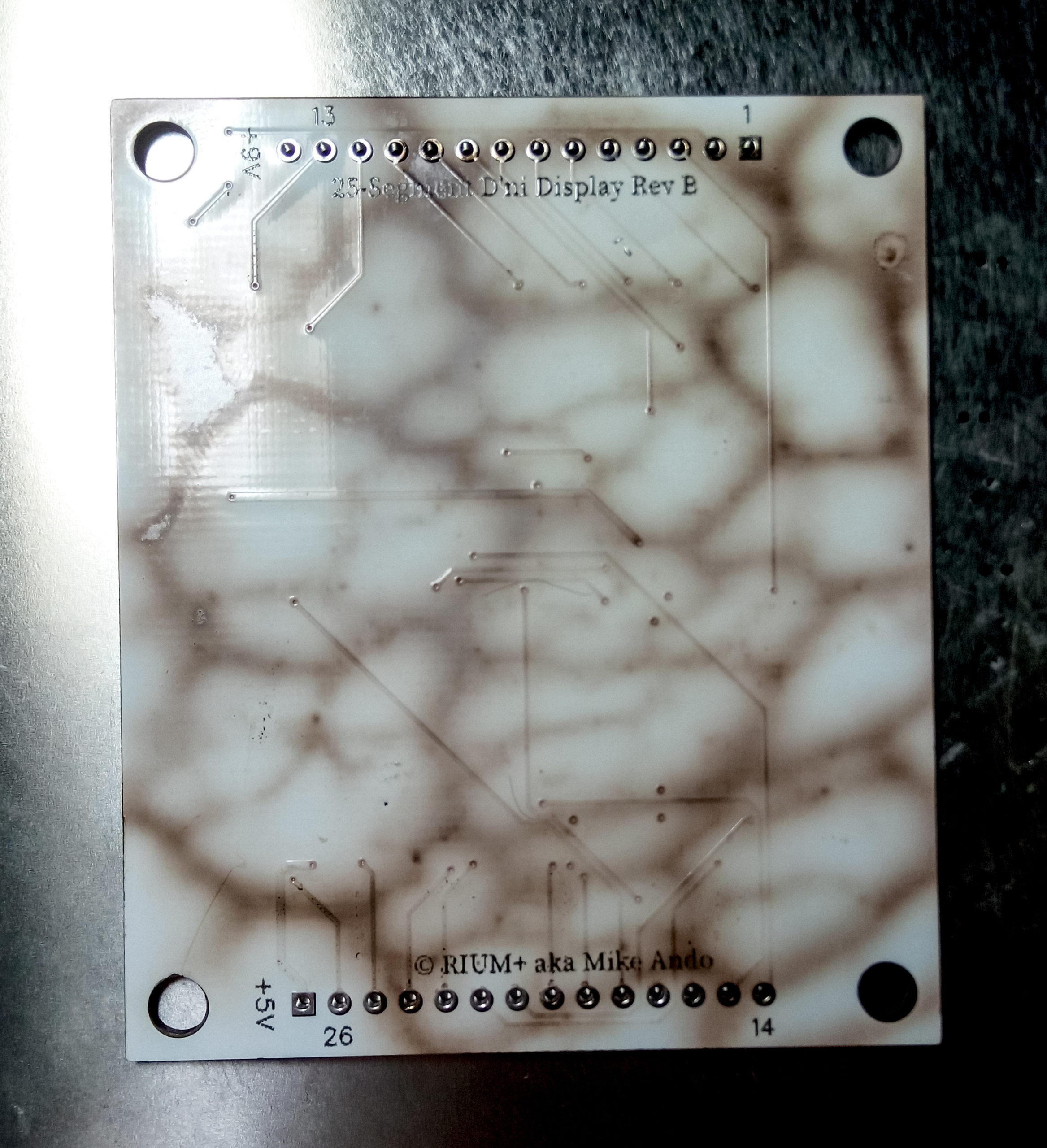
The custom circuit boards were all made in EasyEDA, which is simple enough to use that it runs in your web browser. The layout was imported from Inkscape’s SVG and I used that to properly position the LEDs. Each board has 50 individual LEDS in strings ranging from 1 LED to 4 LEDs long. There’s 36 discrete cells, or resin-filled holes in the acrylic, but some are always lit up together so there’s only 26 controllable segments. There were 2 different voltages used for these boards – 9 Volts for the strings of 4 & 3 LEDs, and 5 Volts for the strings of 2 & 1 LEDs.
EasyEDA’s logic-level layout of the 25-segment D’ni Display
Silkscreen layout of the 25-segment D’ni Display
I know a lot of people like to rag on the autorouter feature of EDA software, but for something like this it works perfectly. Aside from a few starting obvious straight traces I put down myself, and a few extra links added right at the end to reduce the chances of the top or bottom planes acting like antennae, everything else was autorouted.
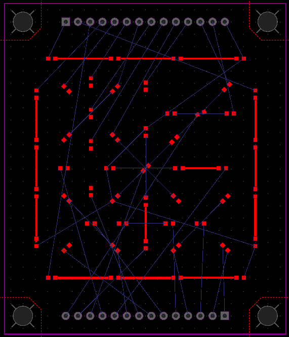
LEDs and a couple traces placed on the 25-segment D’ni Display circuit layout
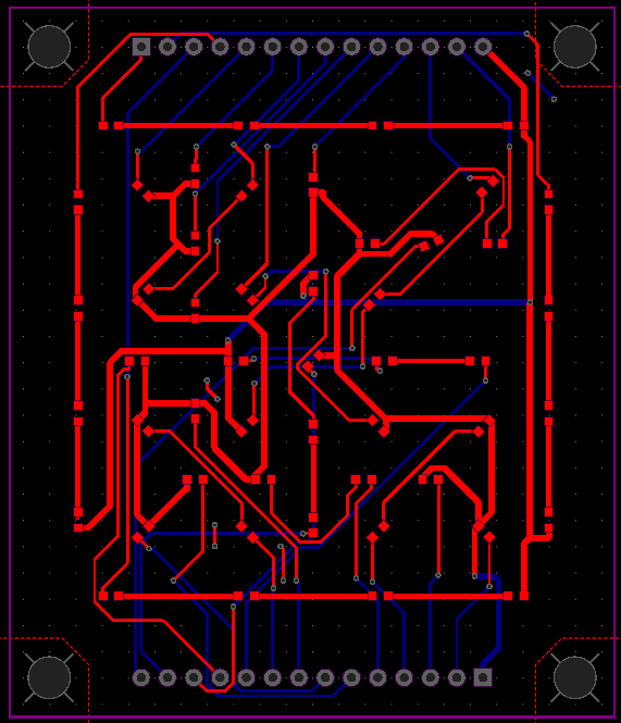
Final circuit layout of the 25-segment D’ni Display circuit, mostly autorouted – I didn’t draw this, it was automatically drawn for me
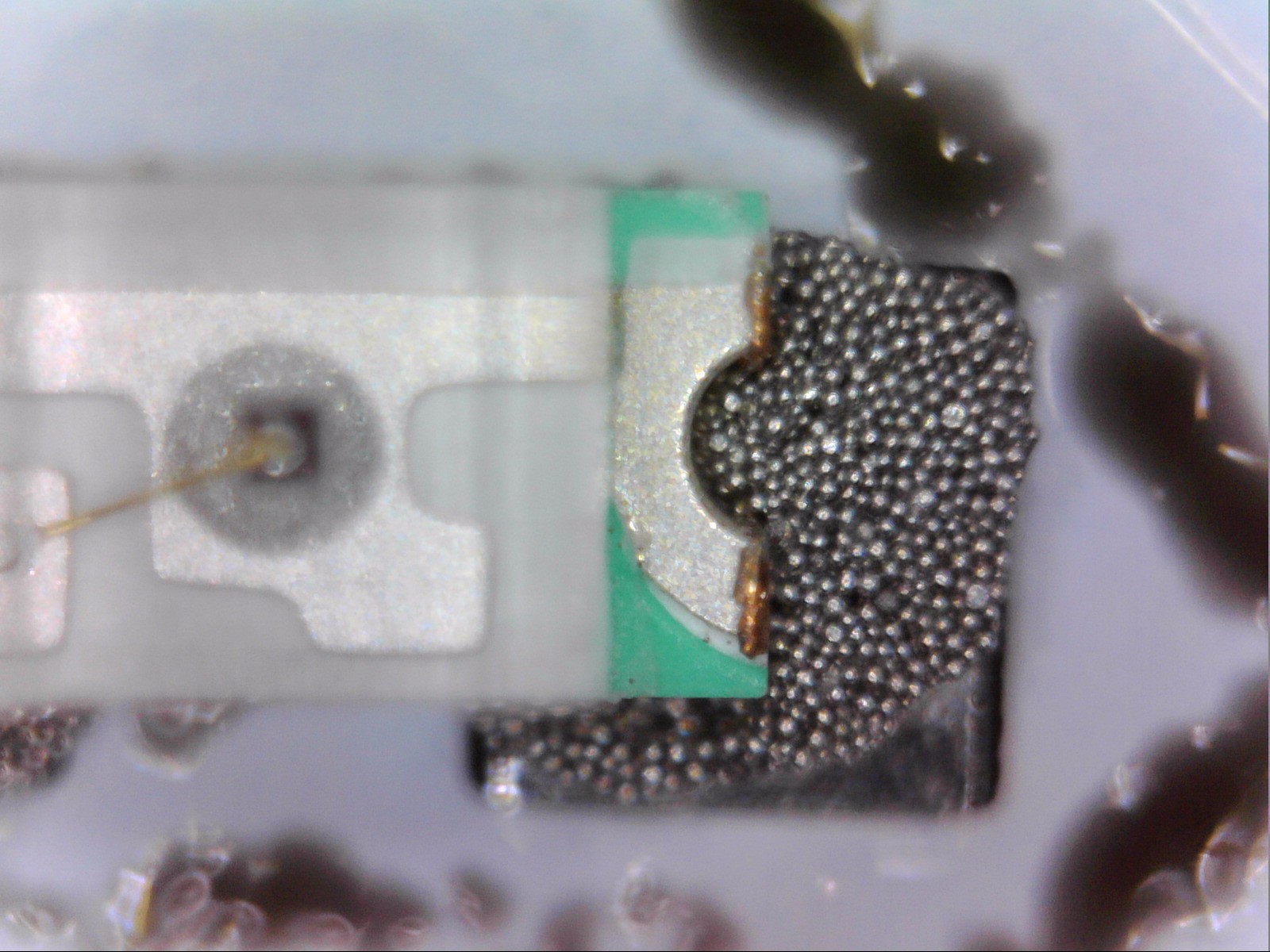
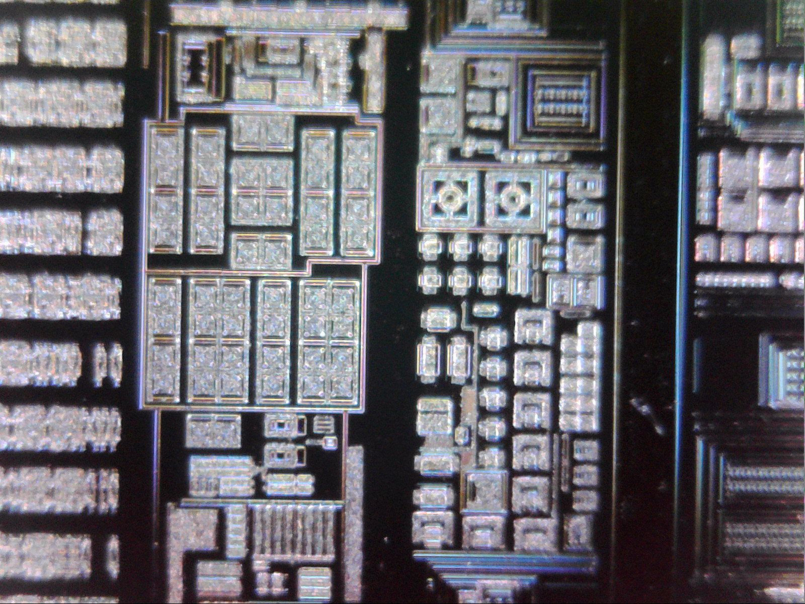
With so many tiny SMD LEDs needing soldering, I definitely recommend paying extra to order a solder stencil along with your circuit board. I have pretty shaky hands due to some medication I’m currently on, but I could manage placing them on the small pads of solder paste left by the stencils. It’s called solder paste but it’s easier to work with (and more accurate) if you think of it as a bunch of tiny beads in oil, rather than an actual paste. If you’ve ever wondered what solder paste looks like up close, here’s some microscope photos!
You can use a fancy reflow oven or an electronics hot plate to fuse the solder, but you can also just use a frying pan on a stove, so long as your pan is actually properly flat. Getting the right temperature is important so check with your brand of solder paste – I used Maker Paste which needs 140’C/284’F. Note that standard cheap IR spot thermometers won’t normally work on metal pans (the pan will reflect the IR light giving a wrong reading), but thermal cameras or cooking thermometers work. One clever hack is to add a few drops of water to the pan & count how long it takes for those drops to boil, add half of that time again, and you should be at around 140’C. Preheat the frying pan and the moment the paste all melts & goes shiny, remove the board from heat – this should take under 10 seconds.
Frying pans totally work as reflow ovens
Pro tip – you can use baking paper to help make it easier to pick up when you’re done, but make sure you use paper that’s rated for whatever temperature you’re using. This is what happens when you use cheap paper that’s not rated that high. Oops. Made a super pretty pattern, though.
I asked a couple dozen people for guesses on what made this bubble-like burn pattern and no one guessed baking paper on fire. Go figure.
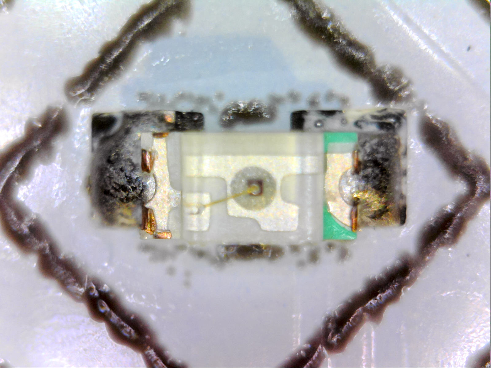
And here’s what they look like with the solder paste melted solid. Note that you don’t have to actually get the LEDs perfectly lined up when you’re using solder paste to do SMD soldering, if you’re slightly off then surface tension will (hopefully) pull them all into near perfect alignment.
I tried 0804 LEDs but they were too big to fit within the segments so I dropped down to 0603, which if you don’t know what that means, they’re 0.06 inches by 0.03 inches, or around 1.5mm by 0.76mm. This is 100% tweezer territory. Here’s a size comparison for you.
Hi I’m a tiny 0603 LED! These are my friends, a US penny and an Australian 5c coin!
Here’s what the circuit board looks like all lit up
Here’s what the final thing looks like with only one layer of diffuser over the top! It honestly could’ve been fine like this, but because I went the extra mile and made 2 diffuser layers, those segments are more evenly lit than the standard 7-segments I used for the normal digits!
Just because, this is what the digit circuit boards look like with a thermal camera, which is a great way to make sure that all the connections are good. This step certainly isn’t necessary, but I have access to a thermal camera with work, so I figured why not use it.
Thermal camera photo of a D’ni digit
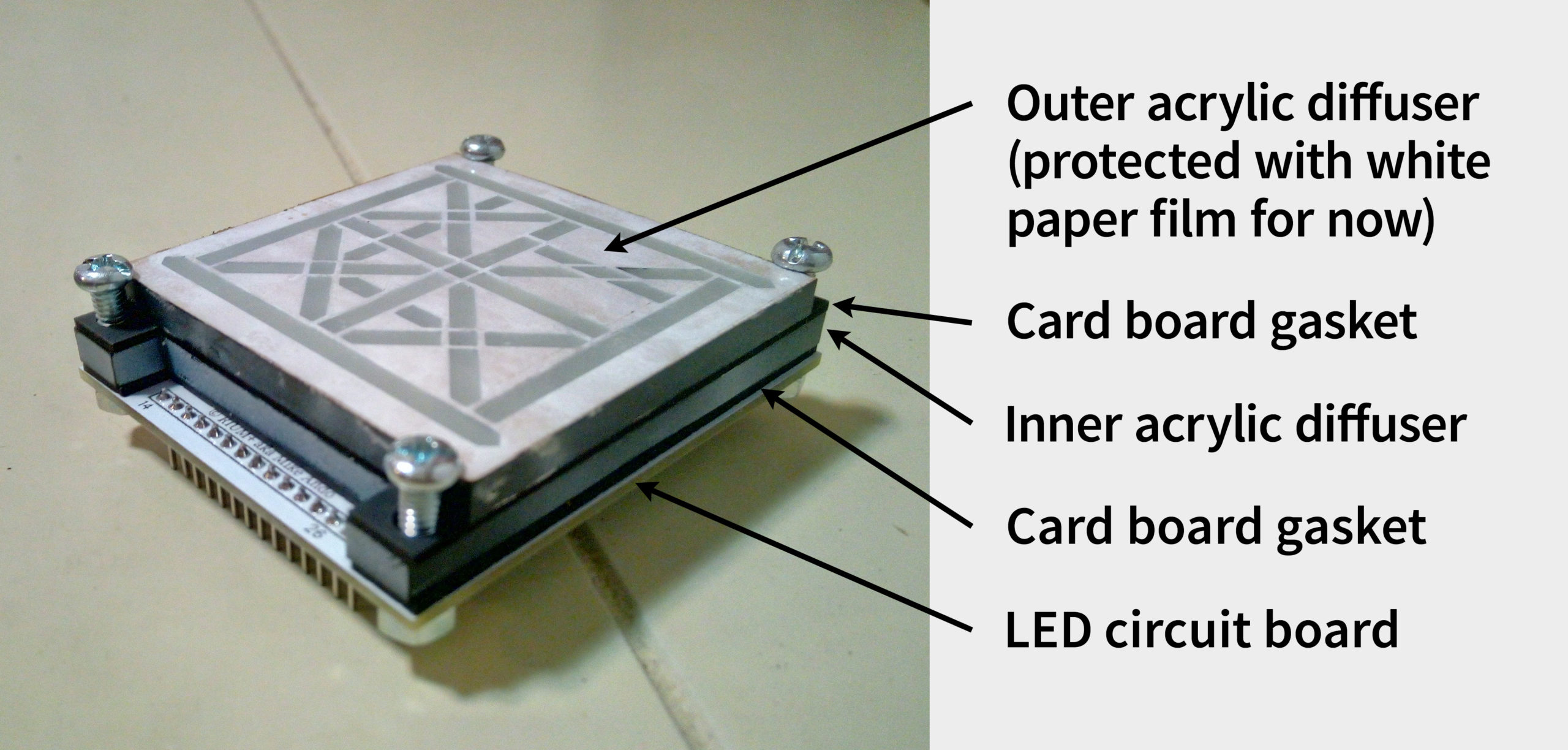
Put this all together, and you get a finished 25-segment display module for showing D’ni digits! The screws are carefully positioned so the threads will go through the case but the head of the screws overlap the modules to hold them in place. Here’s what they look like – layered like an onion, or maybe an Ogre.
Overview of the layers of a 25-segment D’ni Display Module
Here’s what the insides look like without any wires connected. Bottom left in pink are some TLC5947 constant-current variable brightness LED drivers, and they’re sitting in standard off-the-shelf breakout boards with heatsinks attachedto them. These are what turn on/off all the LEDs behind the D’ni digits. Bottom right is some power supplies to convert the 9V in to the 5V some chips require (this takes some of the heat load off the TLC5947’s for the segments with only 1 or 2 LEDs in them).
The inside of my 25-hour D’ni clock, without any wires connected. The top right is a voltage level converter that I screwed up its size in the circuit board design step, so I just extended it up to have enough room to fix the error
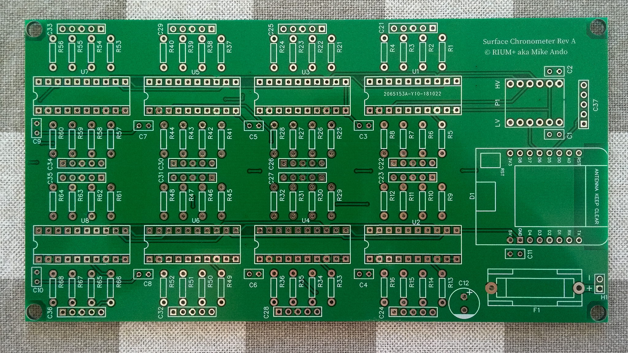
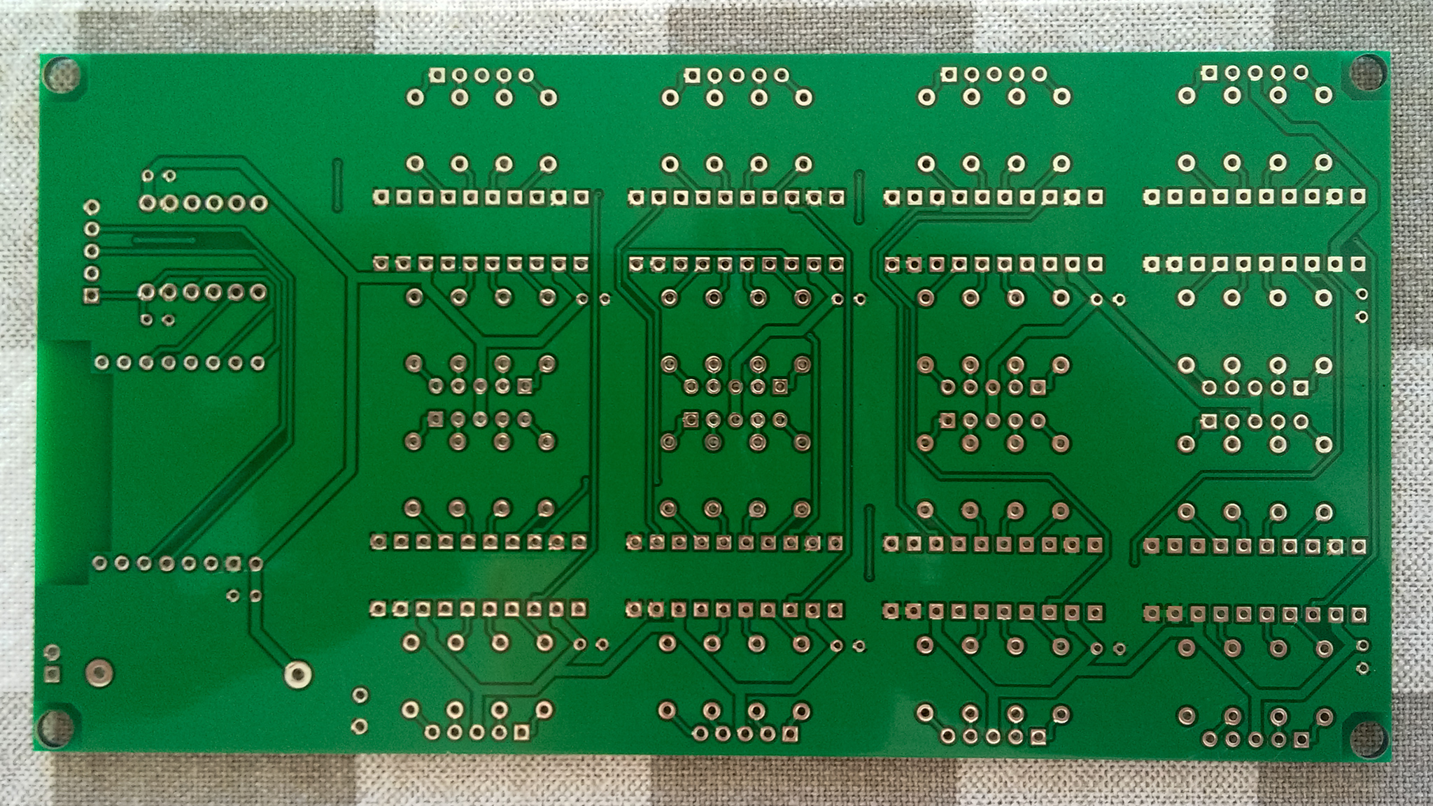
Top middle is another custom circuit board with high-current shift registers to display the “normal” digits. This whole board was designed to be through-hole, as an “easy” design for a beginner solderer to start with. The reason why I’m using a bank of shift registers to control all the LEDs instead of just alternating between them in banks is that this means the display has no flicker and still works during high-speed/slow-motion photography experiments – which is part of what makes it a chronometer and not just yet another fancy clock. Rounding it off is the guts, a branded (not Chinese knock-off; they often have bad power regulators) WeMos/Lolin D1 Mini ESP8266. Having 802.11n-speed WiFi capabilities means it’s already equipped with a reasonably accurate Quartz crystal, to the point that I found an external timekeeping regulator like a temperature/oven based crystal to be unnecessary. The logic it runs isn’t too complicated – connect to the nearest available WiFi point, perform a geoIP lookup, perform a timezone lookup for that location, then poll a few of the nearest NTP servers every few hours. The initial sync is pretty much always within 3ms, and by keeping track of the ESP8266’s clock drift as well as the latency/jitter to the nearest NTP servers (plus a few additional tricks like time of day to estimate the crystal’s temperature variance and waiting for a quiet moment on the WiFi network before transmitting to reduce jitter), its accuracy is refined with each update. Internally it calculates its accuracy in picoseconds (that’s the unit prefix smaller than nanoseconds), but that’s mostly because I’ve been stung enough times by weird edge cases that I try to avoid floating-point maths wherever possible. Officially I’m only calling it accurate to within a best-case of 1ms because that’s a nice round number & is already beyond my home DIY abilities to measure or improve, and just to make extra sure I’m not “overselling” its accuracy that’s why the display only shows a 100ms & a 10ms digit, but not a 1ms digit. One hidden feature of this chronometer is because of the choice of drivers used for the LEDs, I can fully control their brightness and not just turn them on or off – for instance, at night the display dims and the squares around the D’ni digits turn off so it isn’t blindingly bright if you have to go to the bathroom at 2am.
These circuit boards are held up by custom 3D printed standoffs – sure, I could’ve just bought some, but 3D printing some was cheaper.
This design was very cheap and very modular, but its one problem was a ridiculous number of wires were involved – over 450 (!) connection points, all of which have to be connected to wires long enough that you’ve still got enough space to access them, which occasionally gives signal integrity flickers. If I was doing this again, I absolutely would design the digit circuit boards to at least have the shift registers included on them, to drastically reduce the number of potential failure points.
The final step was to laser cut a box to fit this all within. I used the fantastic online tool Boxes.py to make this happen – this is the “Display Case” option. All I had to do here was place holes for the displays & power cable, then get laser cutting. I recommend doing a small test first to make sure you get the play or burn correction settings right depending on how snug a fit you want. This also shows what the box actually looks like, since it’s so hard to photograph glossy black acrylic.
The warning label is true – lasers are awesome.
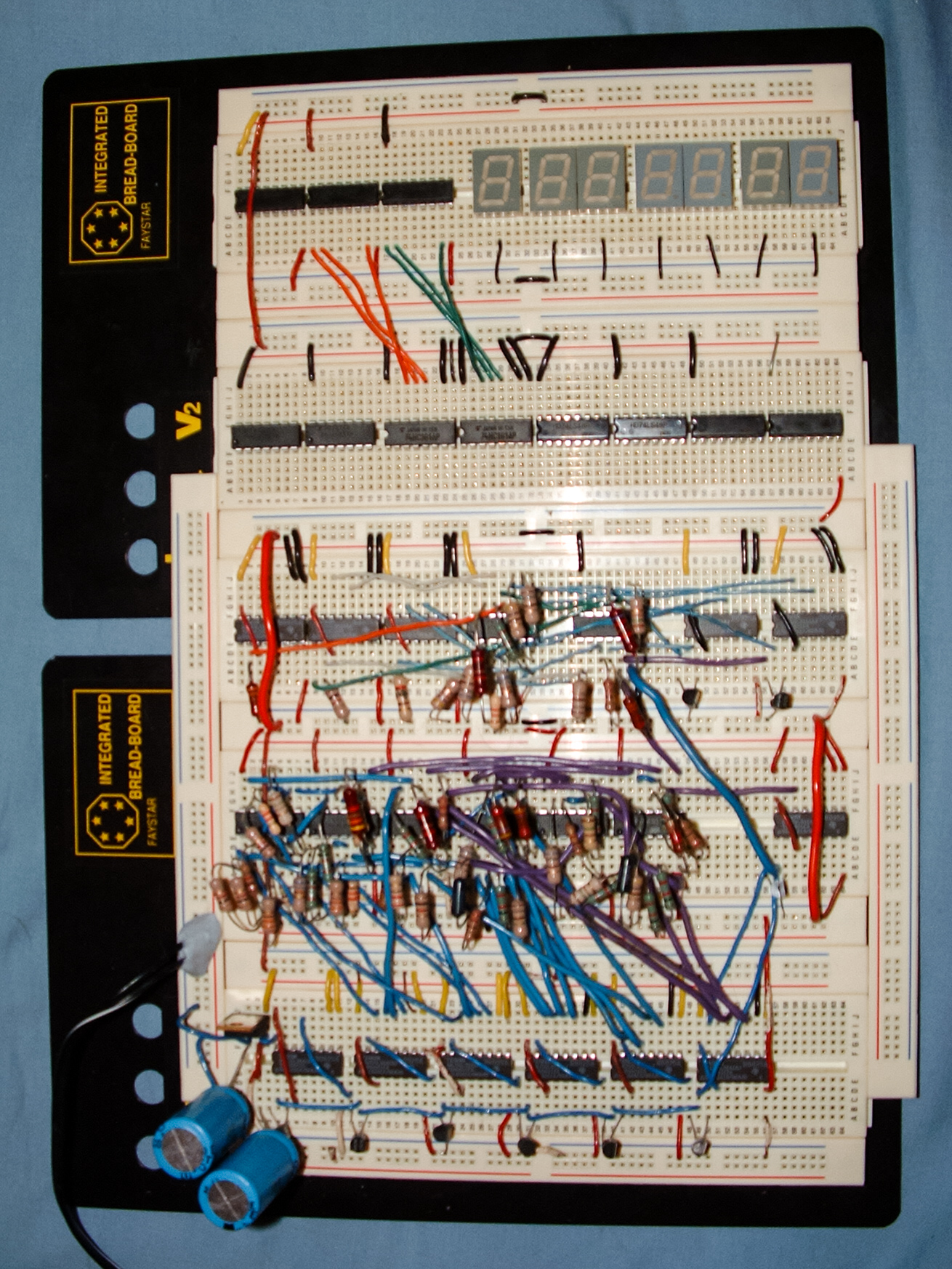
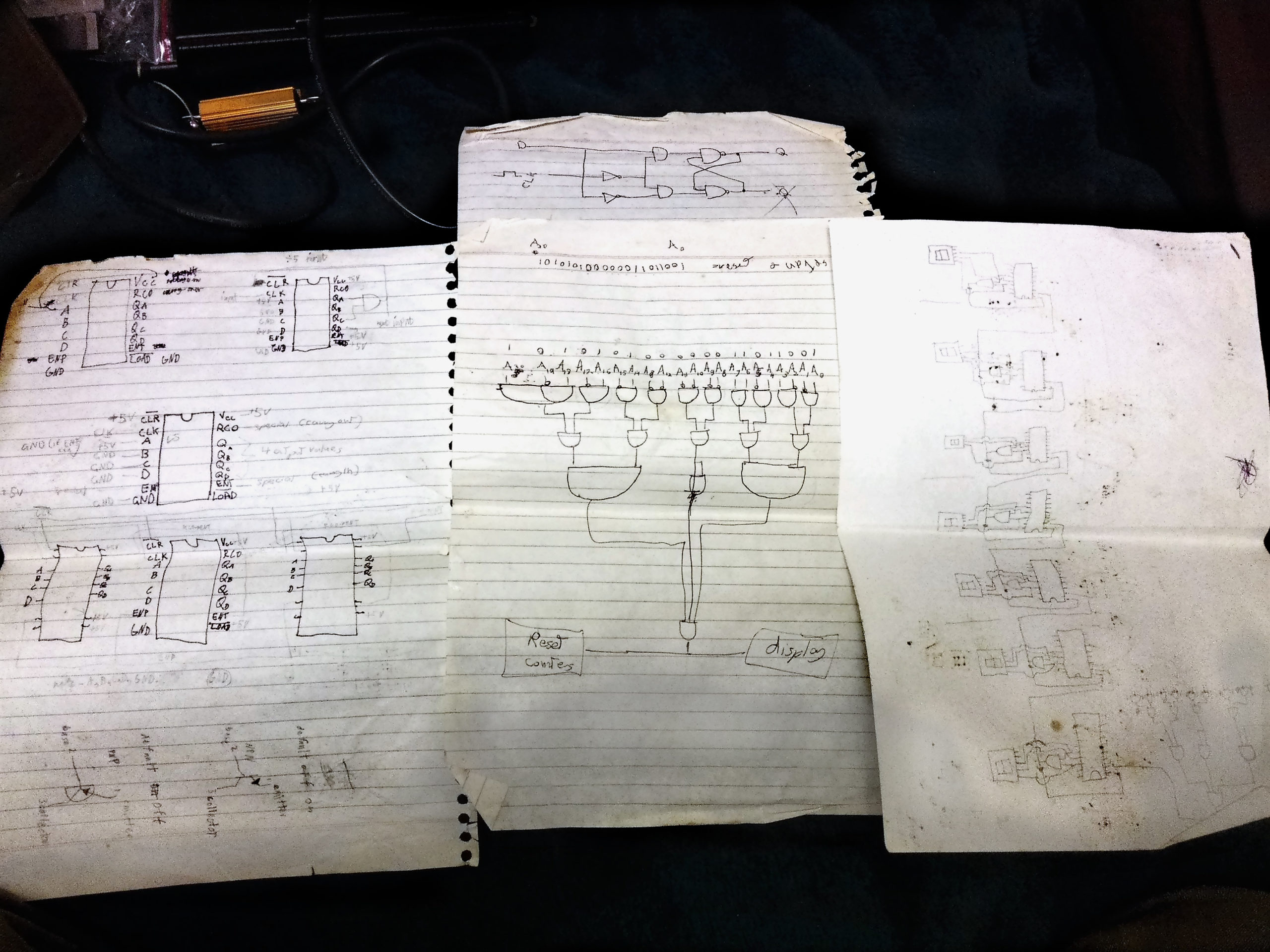
Oh and before I forget – don’t ever give up on your electronics projects just because they seem too hard. I started trying to build this clock nineteen years ago by trying to assemble it out of individual transistors, because modern cheap easy-to-use microcontrollers like Arduinos weren’t a thing, and higher-speed wireless-enabled ones like the ESP8266 were even further away. Building things with electronics is literally getting both easier and cheaper every single year. So if you think something is “too hard” right now, wait a few years and you’d be surprised what other options might be available for you! Here’s one of my failed attempts to build this project from back in 2002 (yes really that old!).
One final final thing – just to show that the 10ms digit really works and isn’t just a random blur, here’s a slow-mo recording of it at 240fps.
(YouTube link in case the above video doesn’t work for you) (Before anyone tries to correct me – yes I know there are technically 36 discrete light cells making up 26 controllable segments in these displays, neither of which are 25. But I asked myself “what will people search for when looking to find this project?”, and since D’ni numbers are base-25 that’s what people are likely to use, so that’s why I decided to call them 25-segment displays instead. So there. 😉 )
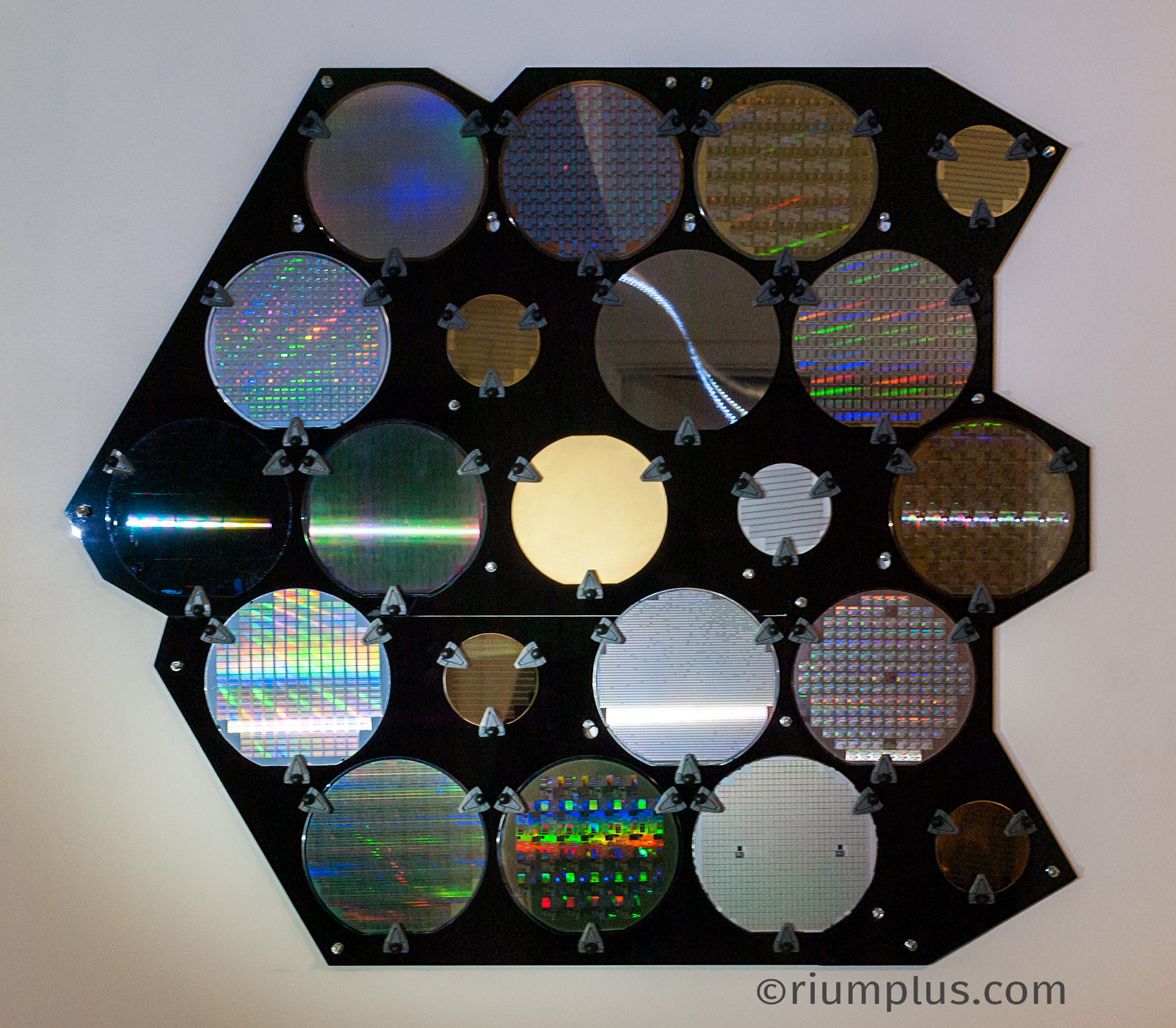
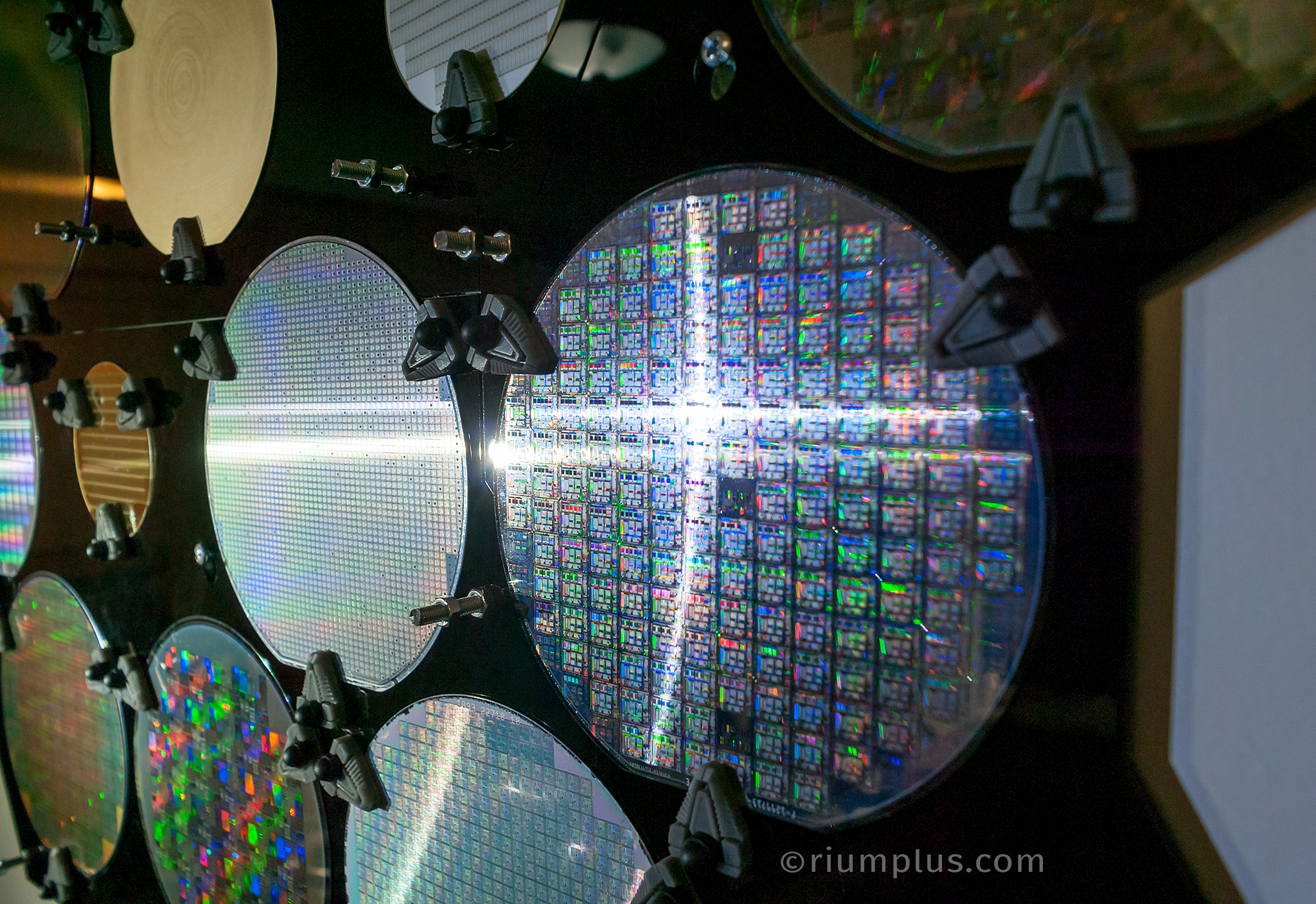
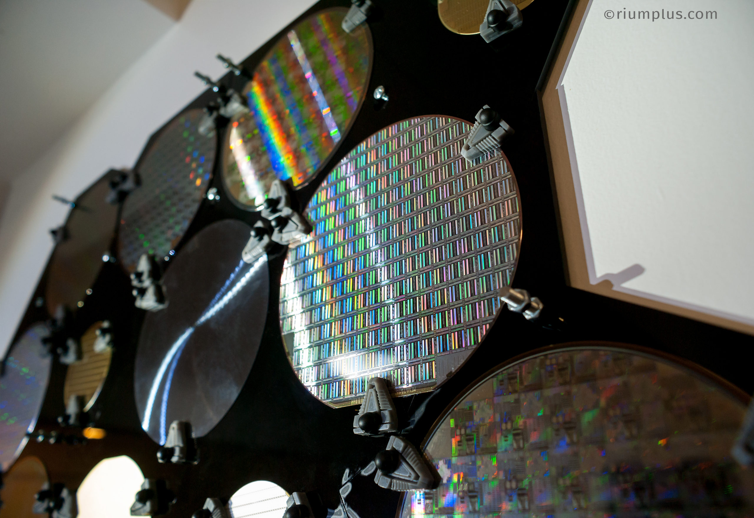
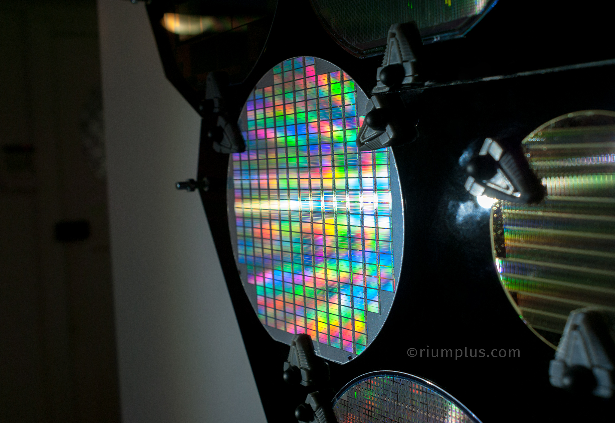
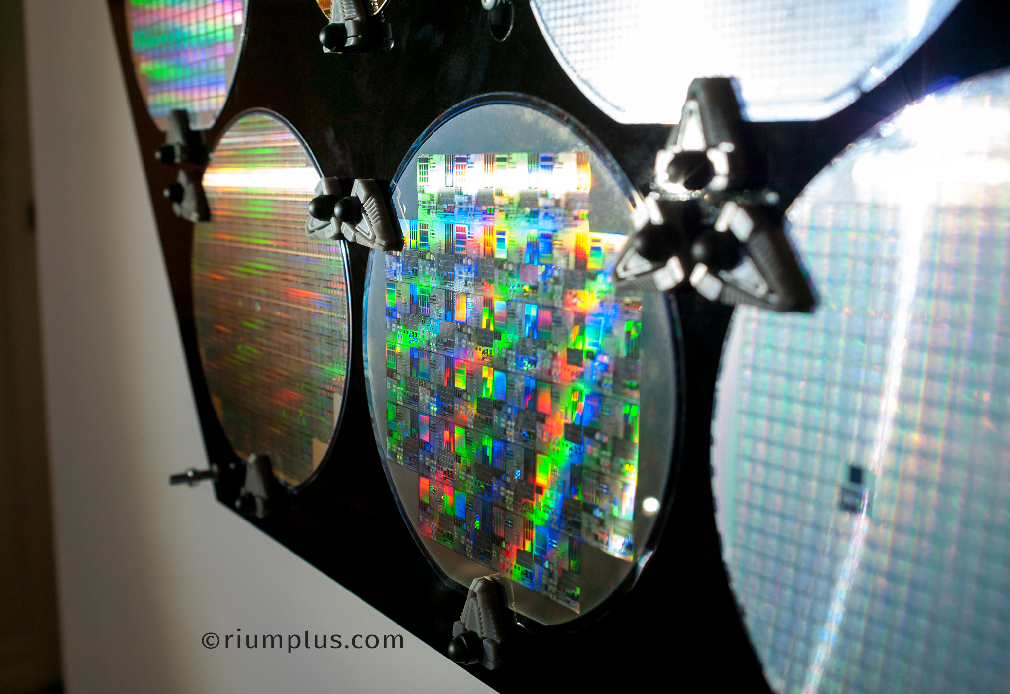
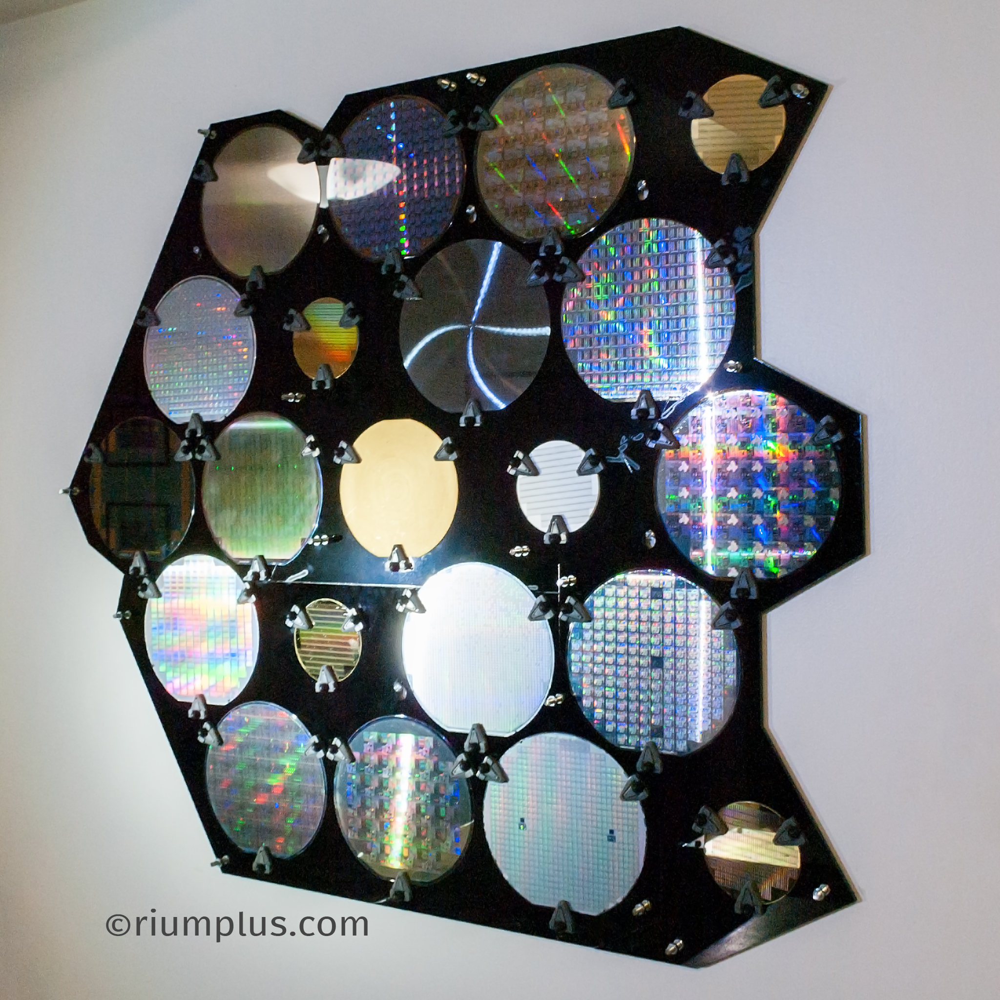
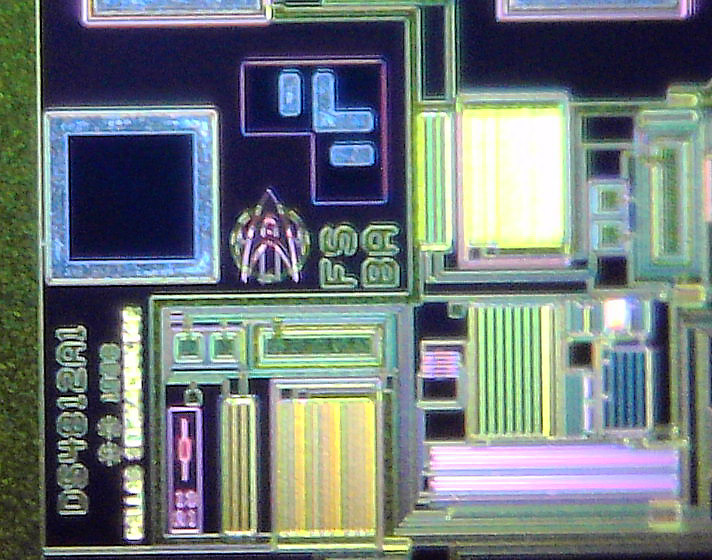
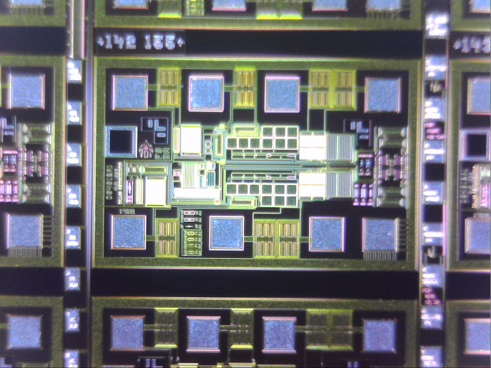
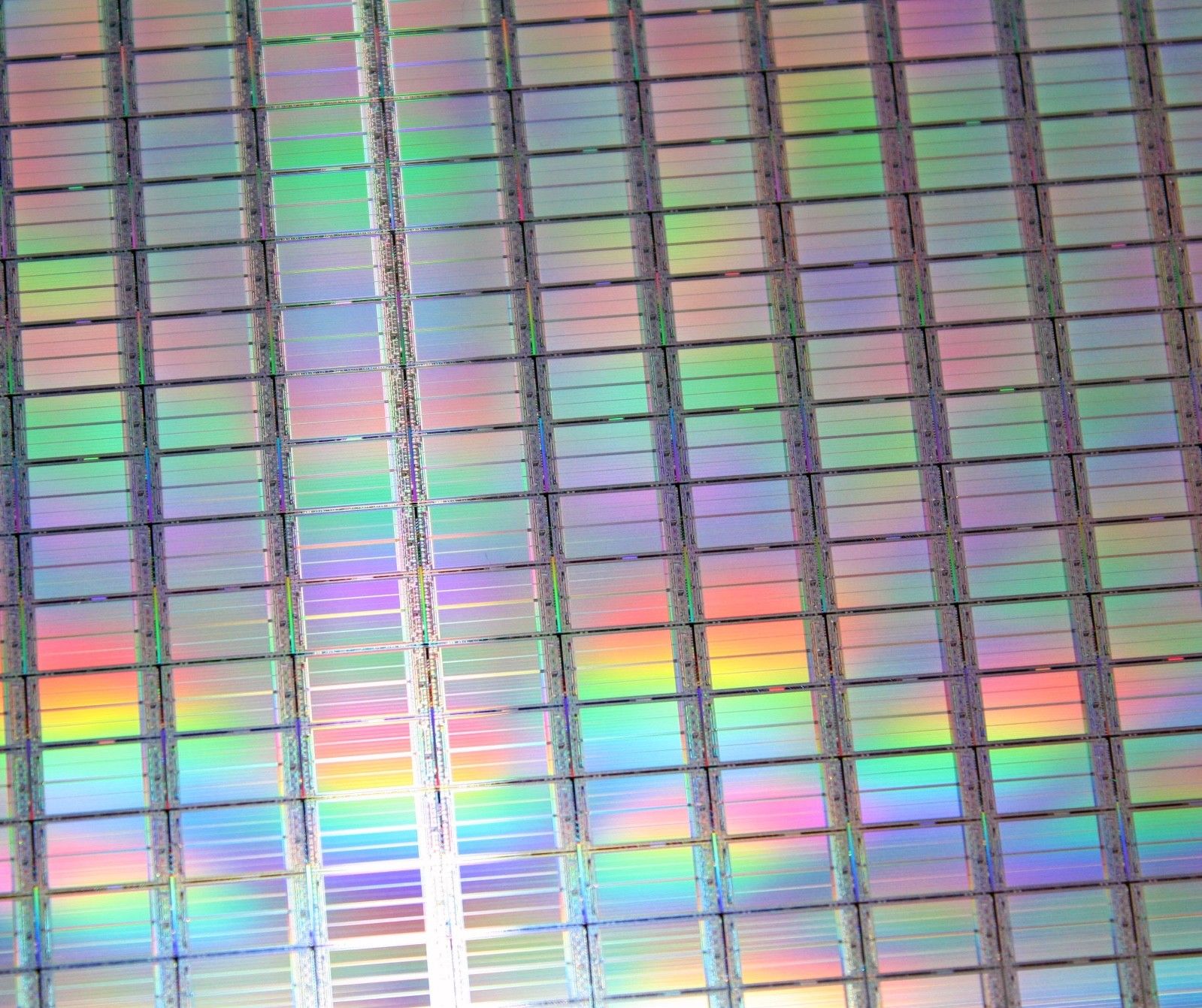
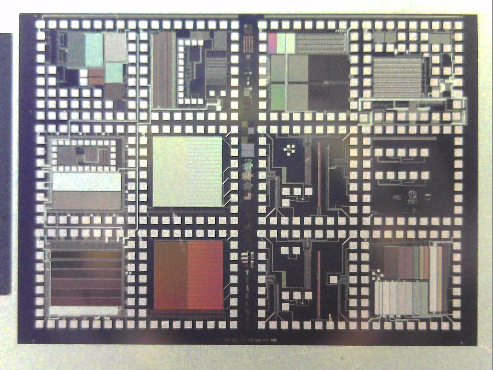
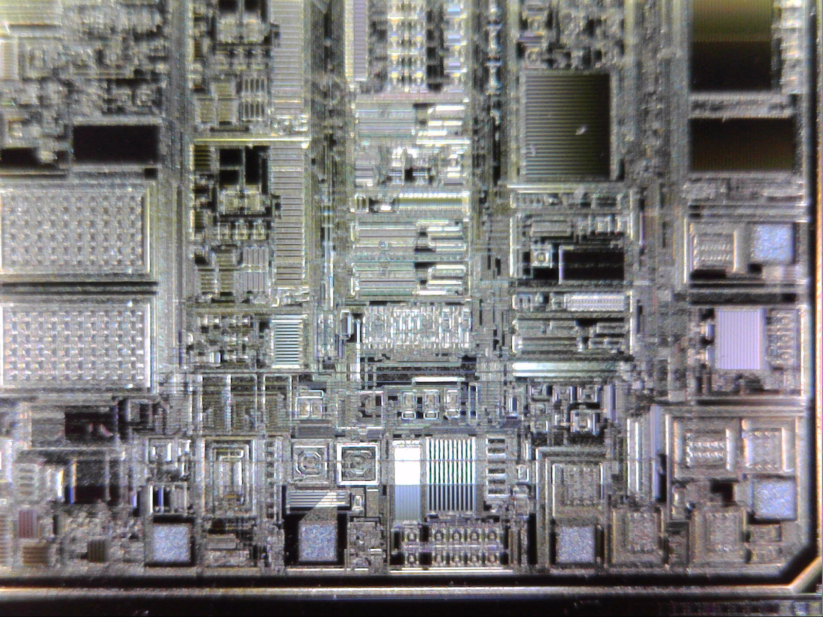
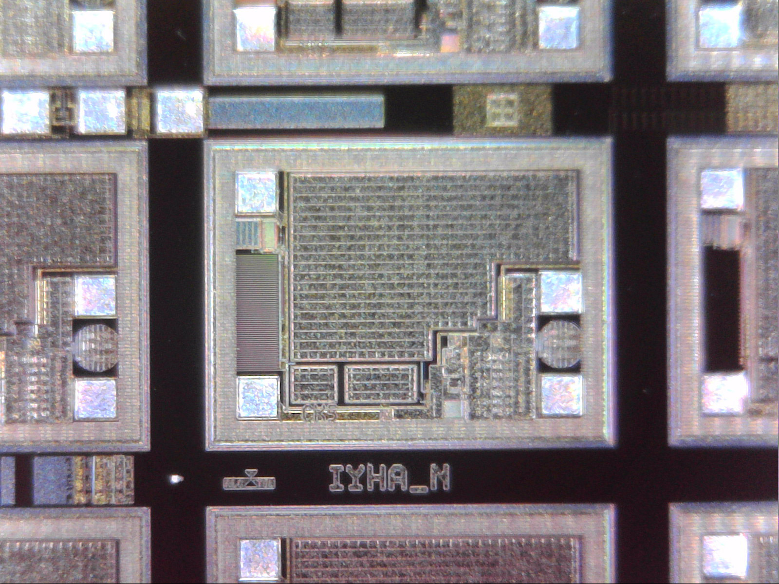
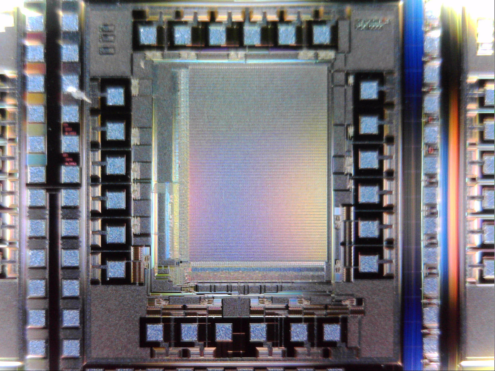
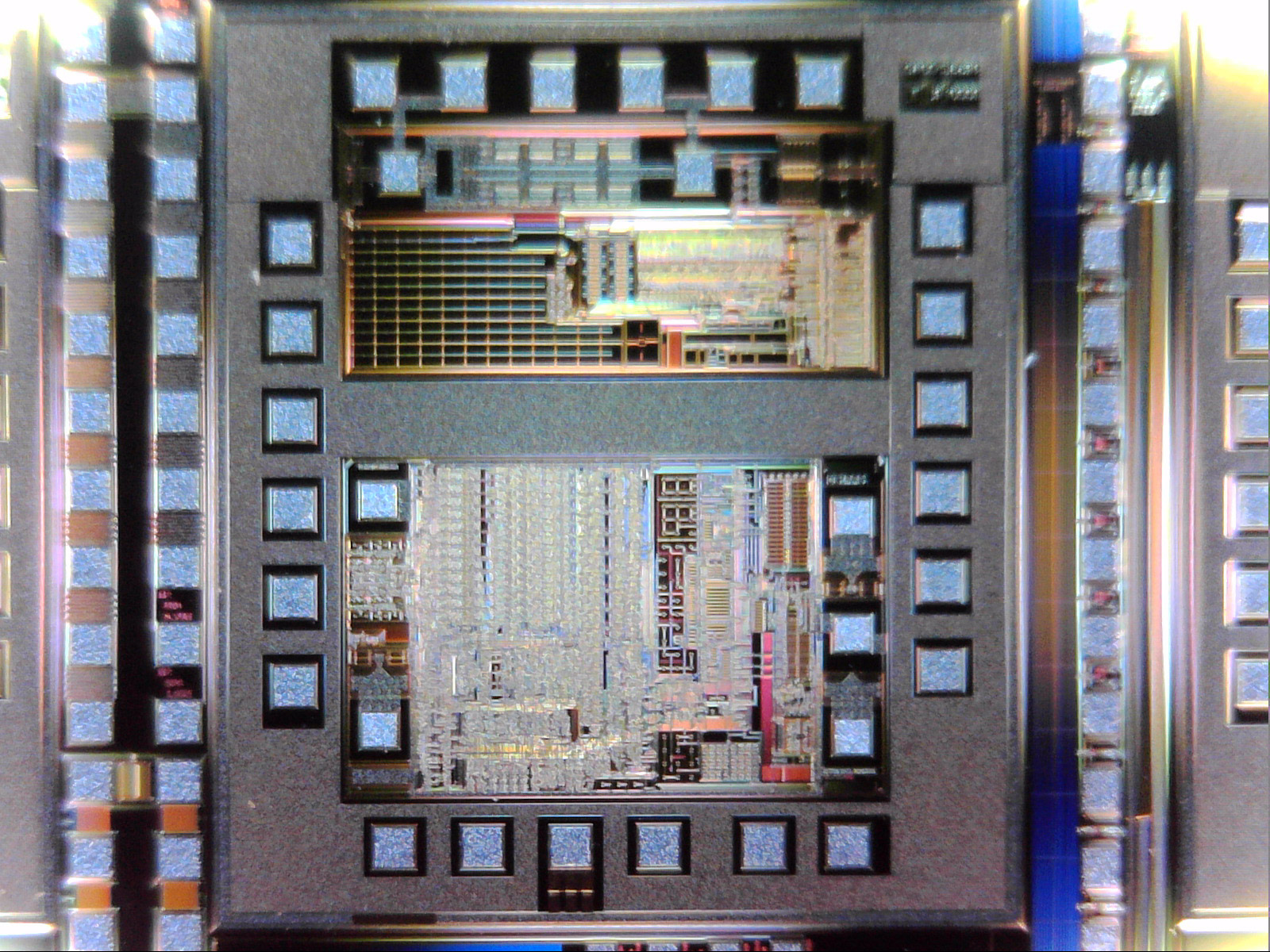
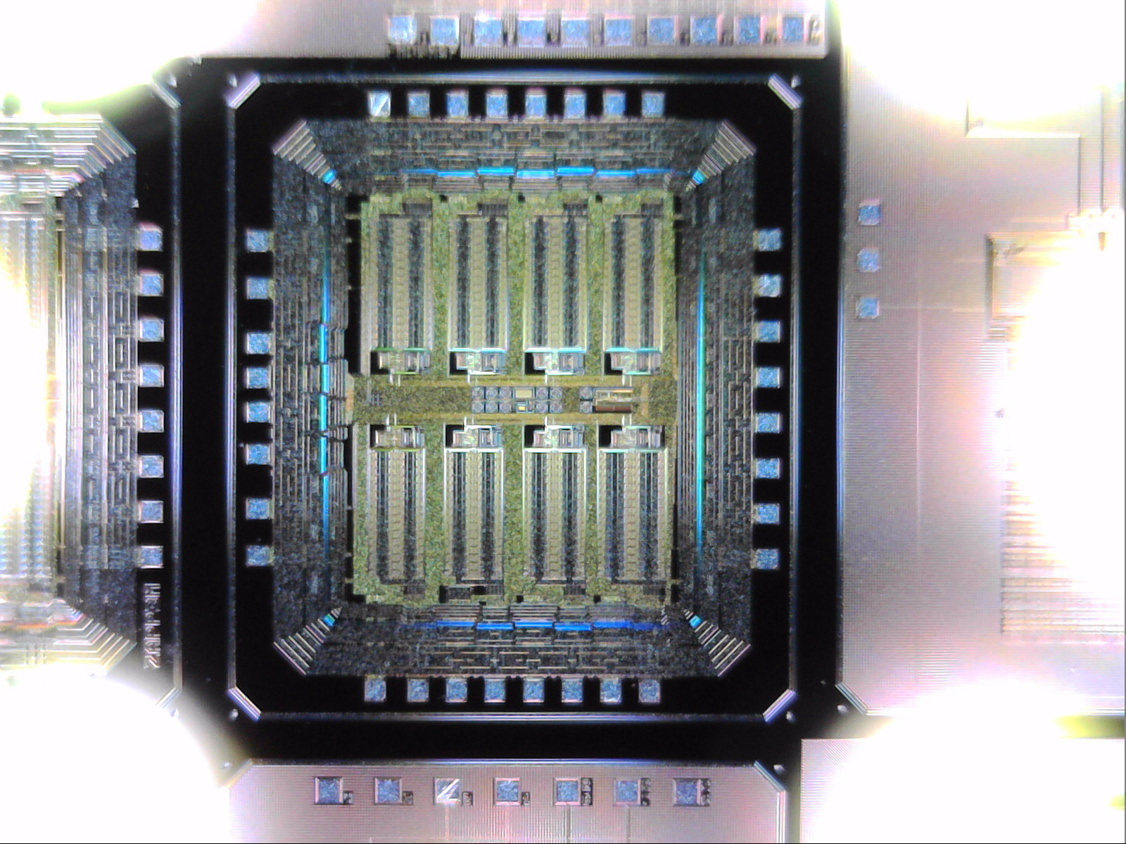
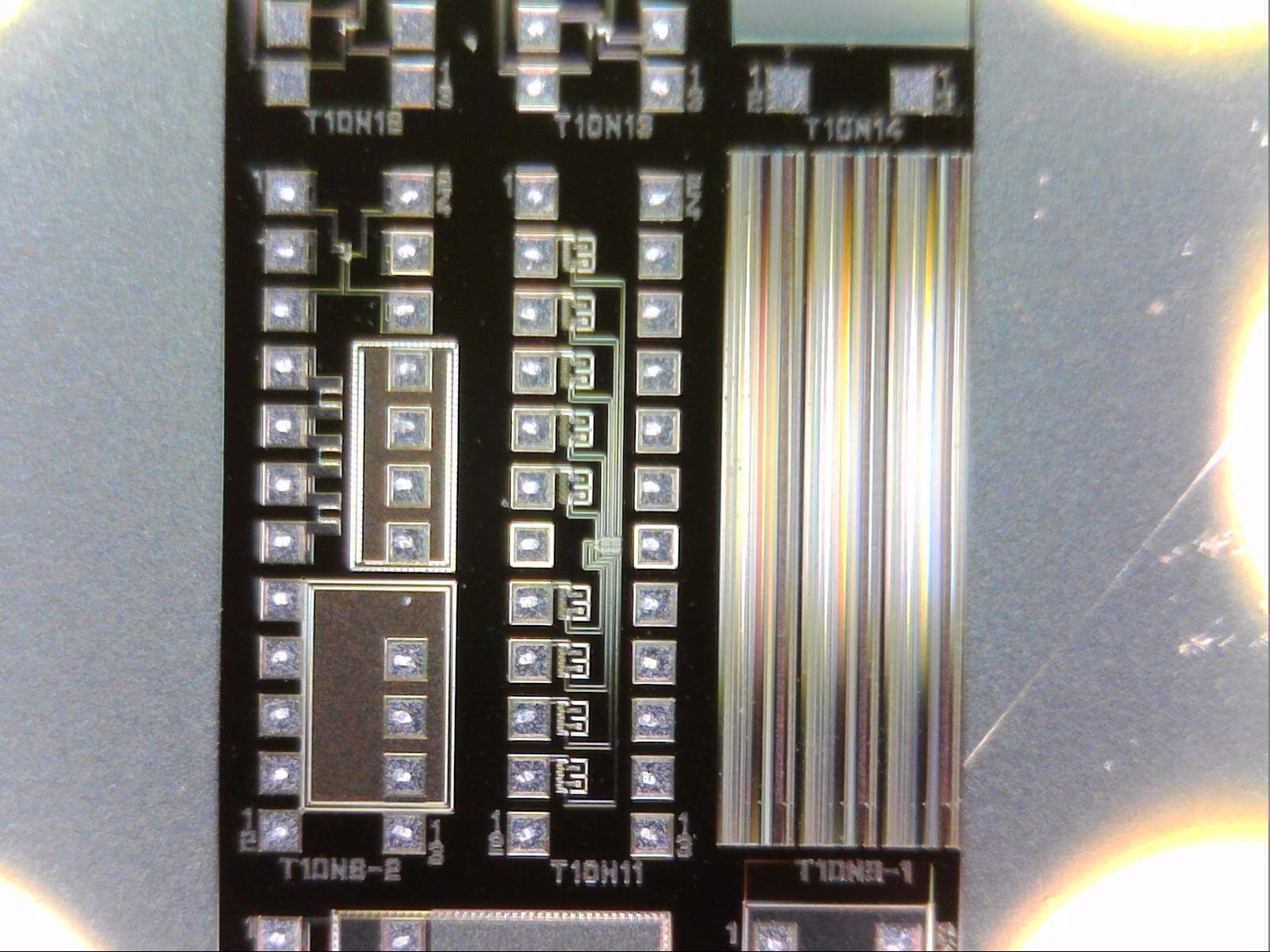
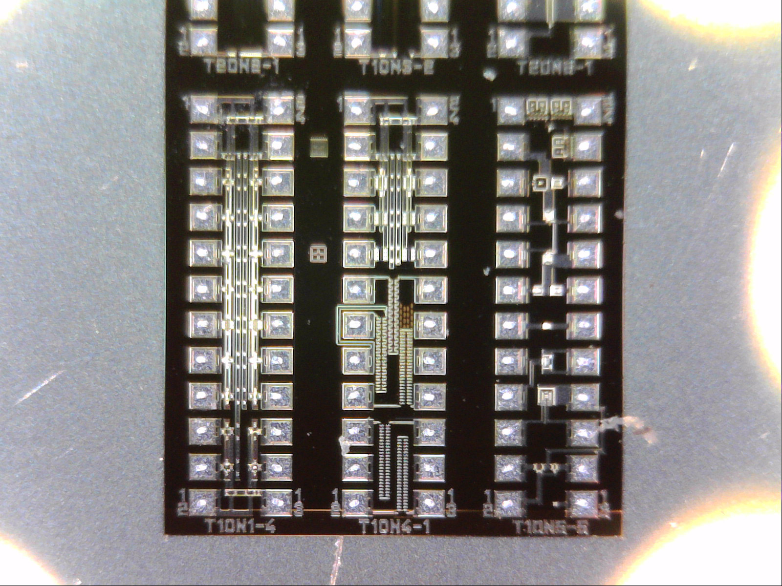
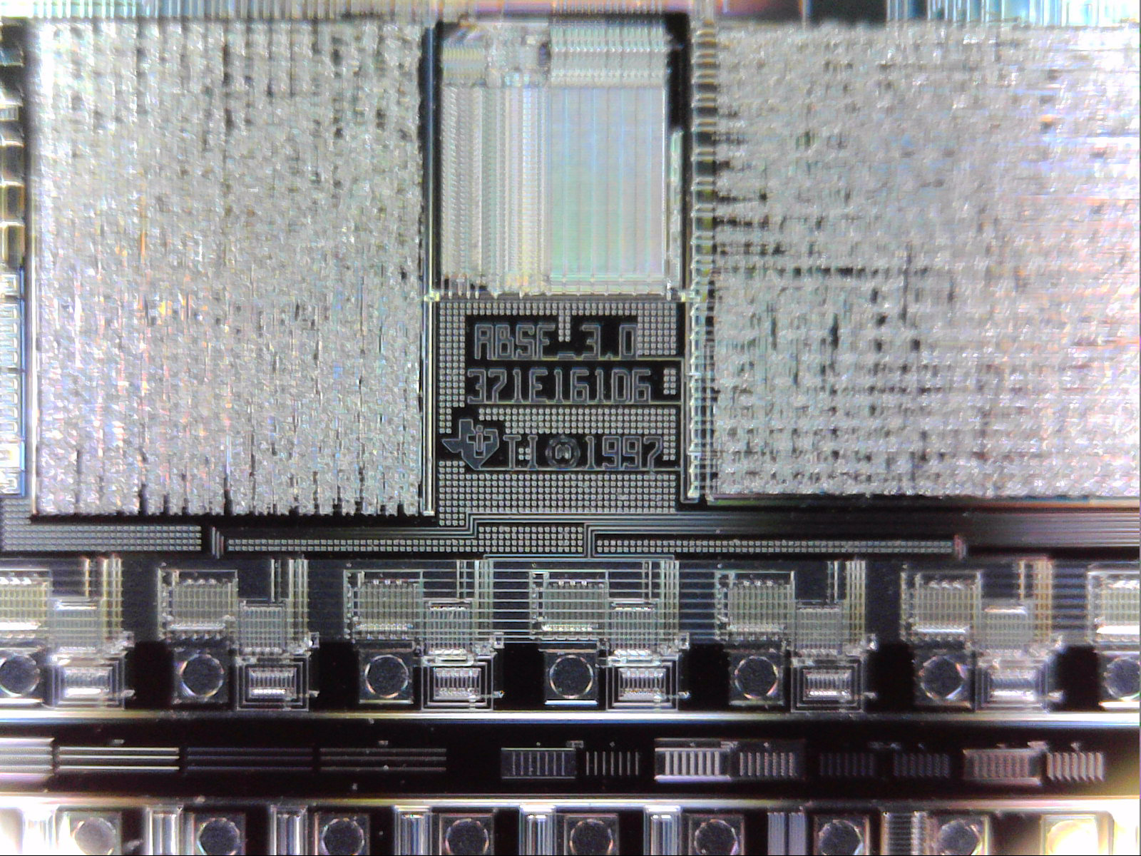
I needed some new art for one of my walls and I thought that this time I’d try making something myself. So I came up with this – an array of 21 Silicon Wafers of various types, styles and sizes. The front and back pieces are made from laser-cut acrylic, and the wafers are held in place with 3D-printed/laser-cut clips based on the Chevrons around the Stargate.
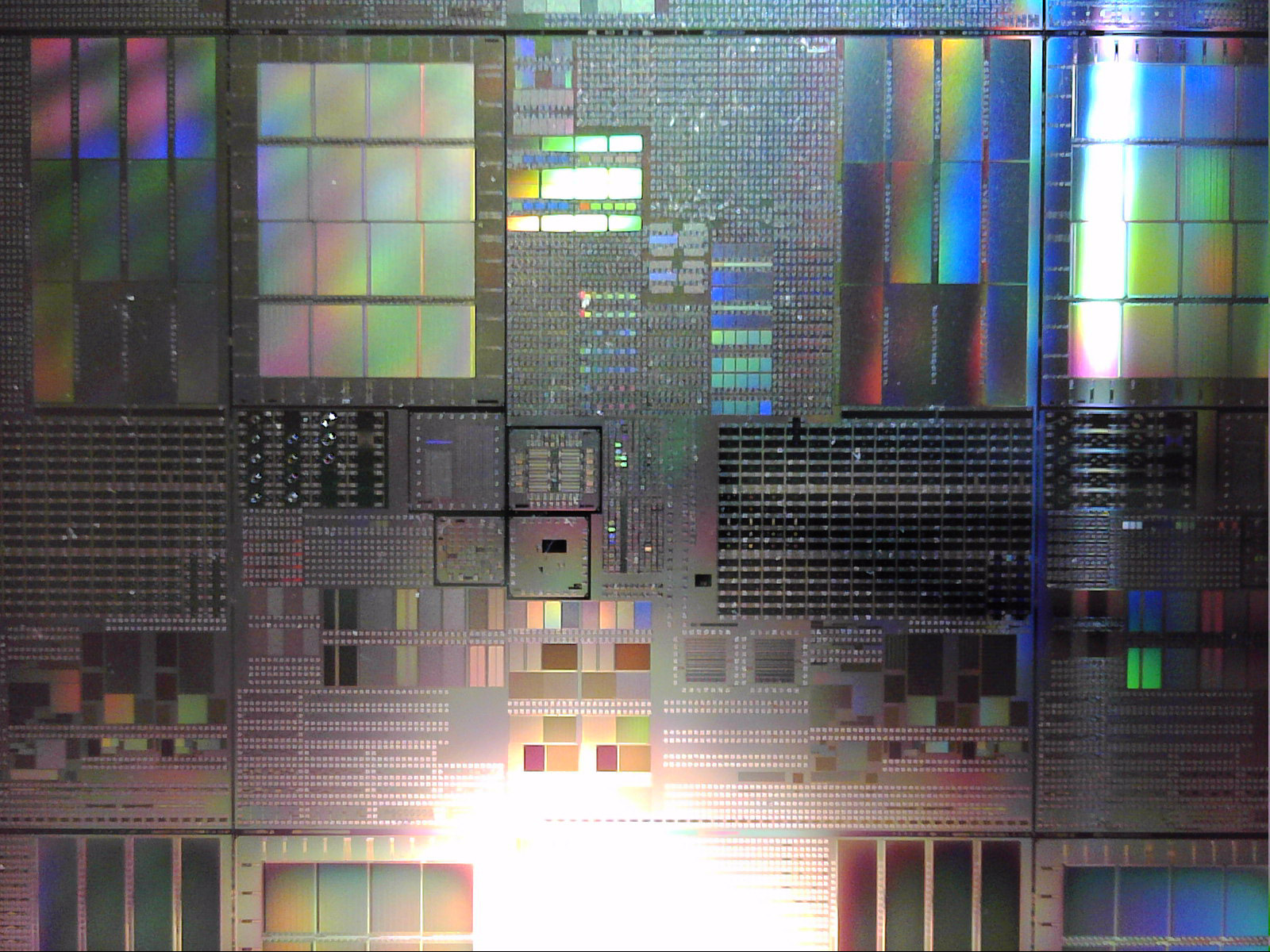
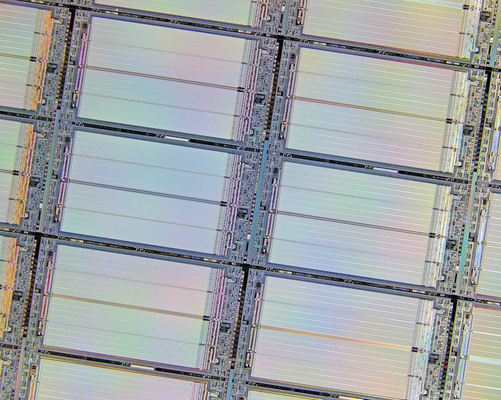
The selection of wafers is as varied as I could make it, made by multiple manufacturers across both Europe & America, from 76mm/3 inches to 150mm/6 inches in diameter, from the late 1970s though to the 2000s. Examples include an 8051-compatible microcontroller, a monitor driver chip, military/industrial grade ruggedised memory, a thermometer (DS1775), a Lexmark printer cartridge chip, an Operational Amplifier (DS4812), a MIPS R3010 floating-point co-processor similar to that used in the PlayStation 1 and the SGI workstations used to render 90s things like Jurassic Park and my favourite game Riven: The Sequel to Myst, Solar Photovoltaic panels, interposers, test patterns, bare unpolished Silicon, and even a thin layer of pure 24k gold.
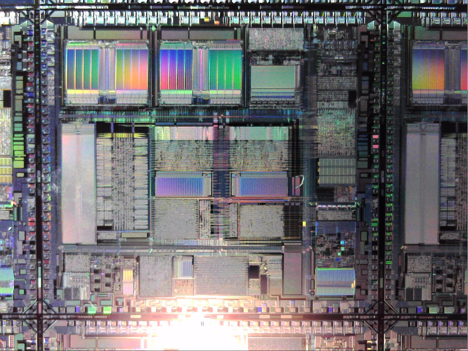
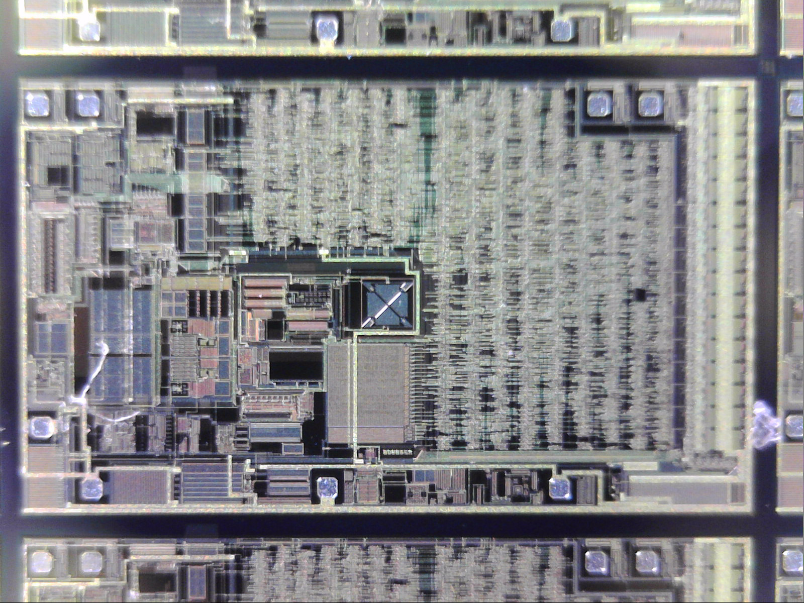
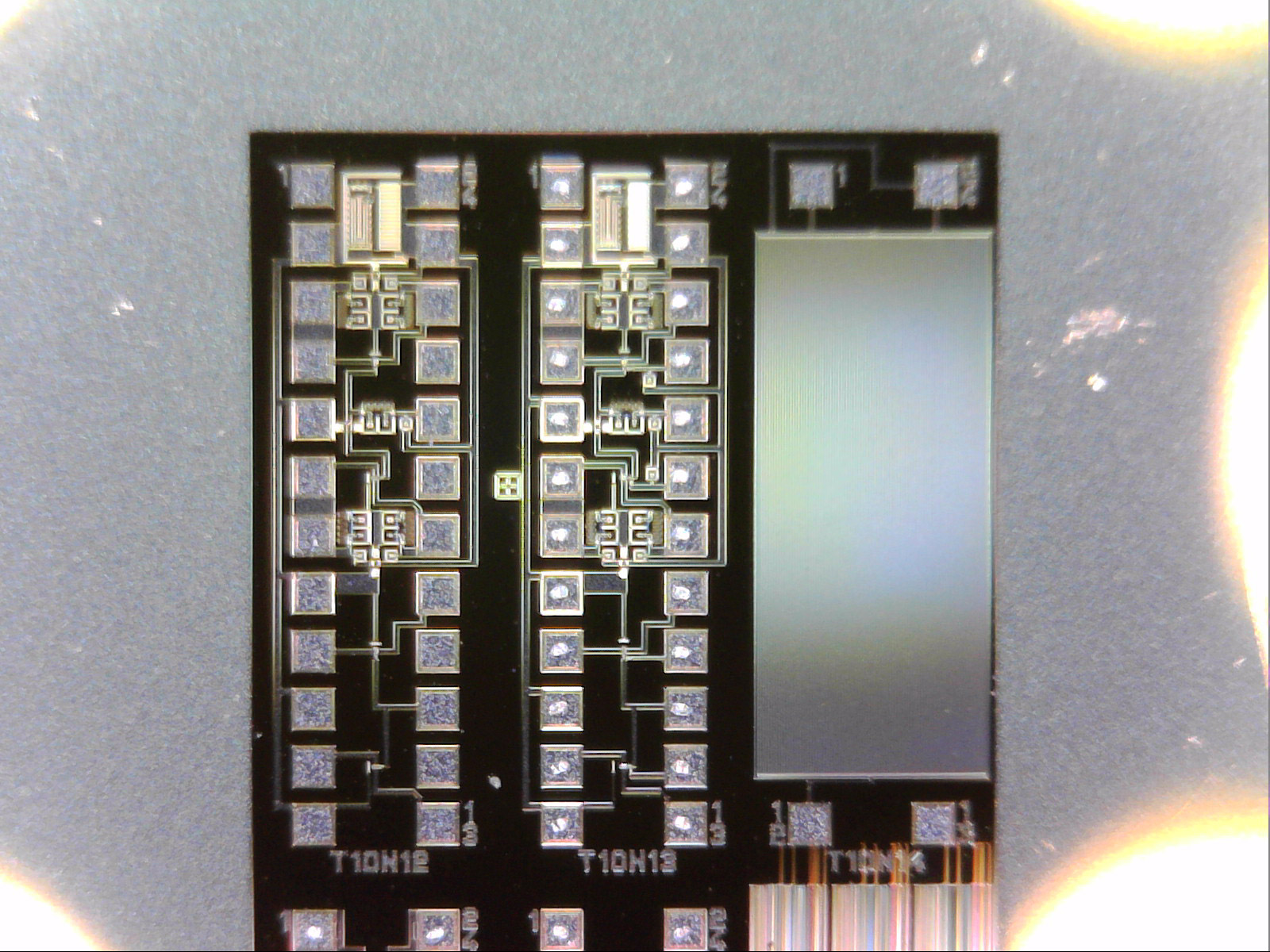
Because the etchings on the wafers are so small, a lot of them produce fantastically vibrant rainbow patterns when the light catches them at the right angle.
Some background if you don’t know what these are: computer chips are created by first growing giant cylindrical crystals of almost-pure Silicon. These are then sliced up into thin wafers and these wafers are chemically etched with all the wires & transistors using mask & a UV light source. Think of it like creating an image on photography paper using shadow puppets & a flashlight. Each wafer normally has hundreds of individual chips, or dies, etched into it. Then they’re cut up, tested, and packaged into their final form. Companies don’t normally sell the raw whole wafers but you can often buy them on eBay, mostly for older wafers and/or manufacturing runs that had defects and were destined for the bin. Prices for etched Silicon wafers vary anywhere between a few dollars to a few ten thousand dollars per wafer, depending on what it is. In total, the whole artwork is made up of many thousands of dies, far too many for me to try and count.
The first step in producing this wall artwork was to create a smaller test version, to see if the whole concept would work & how it’d look, and to iron out any kinks in the process. The prototype I created was made with just one wafer. This wafer was held in place by just the raw screw threads, which didn’t really do a good job to hold it securely in place. Valuable experience gained – come up with a better mounting system for the large design. I used a laser cutter at a lower power level to engrave-remove a few millimetres of acrylic to countersink the screw heads so they didn’t stick out. It took some trial & error but eventually I had it dialled in perfectly so the screws were perfectly flush with the acrylic. This test run was to be a present for my mother, so I picked a wafer that was made the year I was born and shines mostly pinkish (her favourite colour). The actual chips are 256K SRAM memory, so the back’s got a cheesy engraving text about “memories” on it.
Despite some of the wafers being supposedly the same size, I noticed that a lot varied in size a little bit. To account for this, and to hold them in place so they wouldn’t rattle or rotate, each wafer was individually measured and individual mounting spacers were laser cut out of 2mm thick black backing cardboard. Since the wafers are round, I modelled the top holding clips to look like the Chevrons that surround the Stargate. These Chevron clips were 3D-printed on a resin printer – resin printers might be normally slow but when you can print 18 clips at a time, they’re not only quicker than an FDM 3D printer, the end quality is far better too.
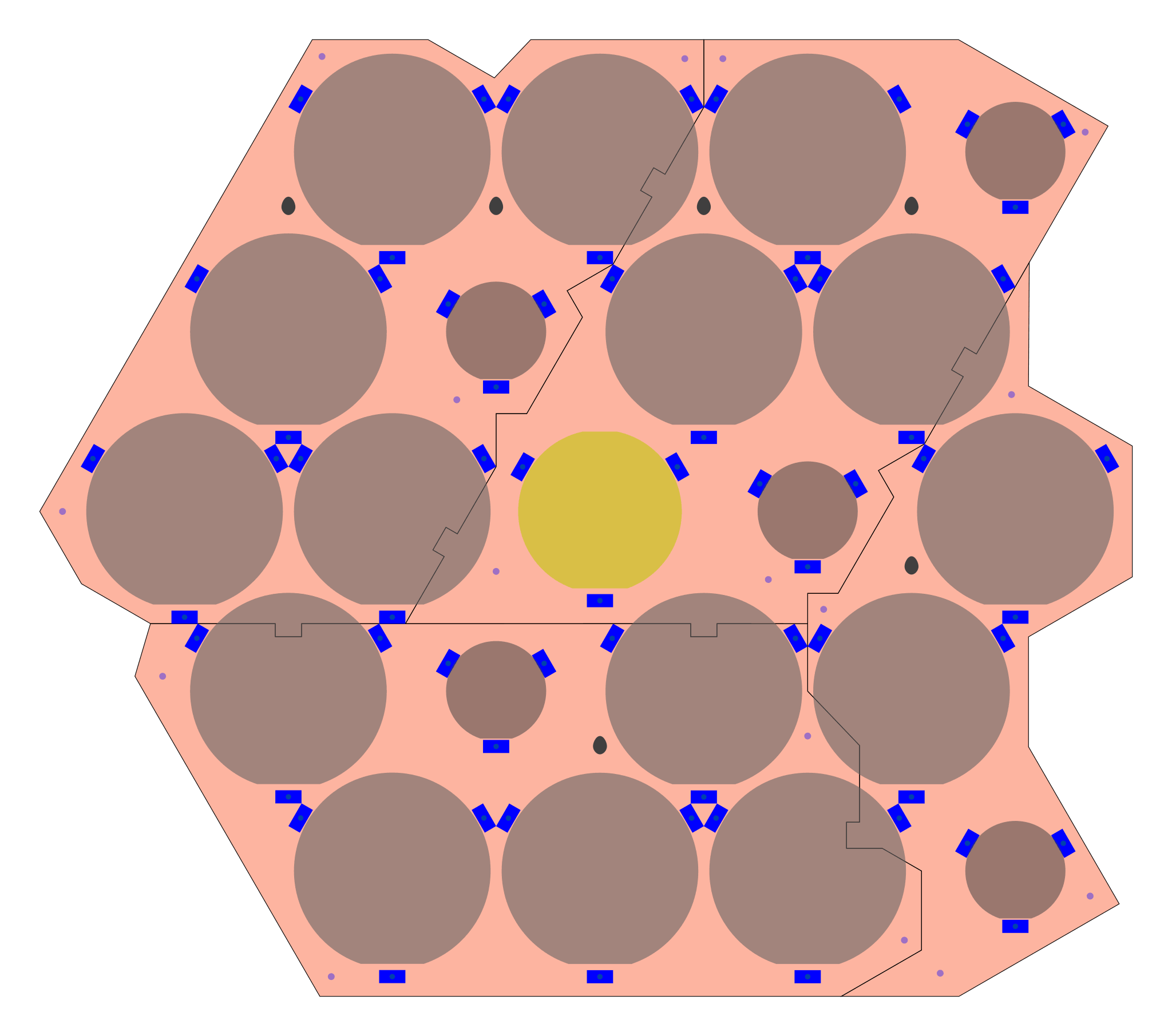
The whole display piece was far too large (730mm high * 830mm wide) to be cut in one go on a laser cutter, so the piece was broken into 4 smaller pieces and glued together. A brutalist aesthetic was adopted for both the jigsaw-like interlocking lines as well as the whole shape. This worked well to hide some of the size limitations so I could get the maximum usable area possible out of the raw sheets of acrylic. For instance, the notch cut out on the middle left isn’t just there for aesthetics, it gives me a couple more centimetres of length for both the upper left and the bottom pieces. Without that notch, neither piece would fit within standard 300mm * 600mm sheets of Acrylic. A top layer of clear acrylic was added to both keep dust away and to protect the wafers. Some of these wafers are so delicate even a single gentle wipe with a fresh microfibre cloth will instantly destroy them (which I accidentally did trying to clean fingerprints off one, oops). It took around 9 months to build, most of which was taken up with trying to acquire as wide a variety of wafers as I could.
When doing any project involving lots of something, it’s important to remember that the time required can quickly balloon if you have to do that job many times over. For instance, there’s 63 3D-printed Chevron clips in this project – spending 8 minutes per object cleaning them up means over 8 hours just cleaning. I tried to keep the part count to a minimum, but even still there’s 21 wafers held in place by 63 3D-printed clips and 63 laser-cut mounting spacers, held together with 63 bolts plus 63 nuts and 63 black end caps, mounted on 4 sheets of black acrylic with 4 sheets of protective clear acrylic over the top, separated by 16 bolts with 48 nuts and 16 end caps… Phew. This all means the total part count for this project was 424 pieces. If I could do it again I would consider removing the laser-cut spacers and merging them with the 3D-printed Chevron clips to reduce the number of parts a little & eliminate one of the construction materials.
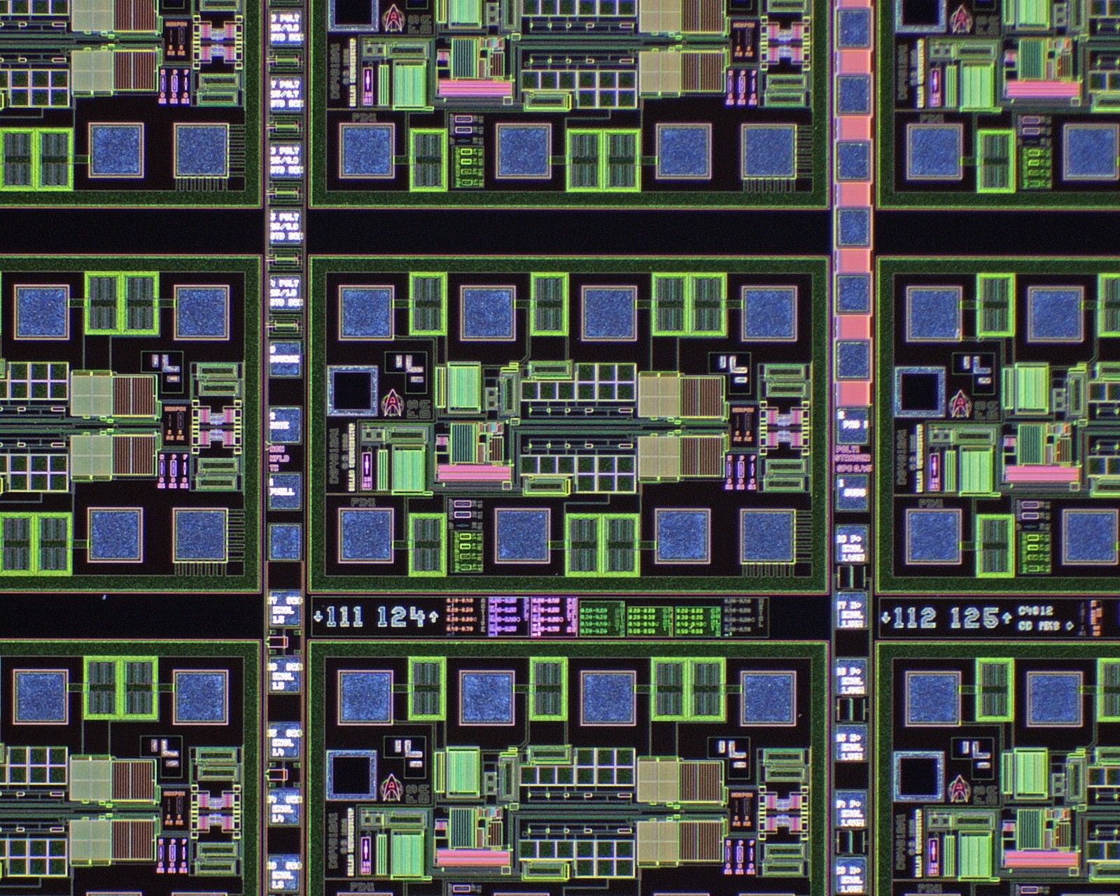
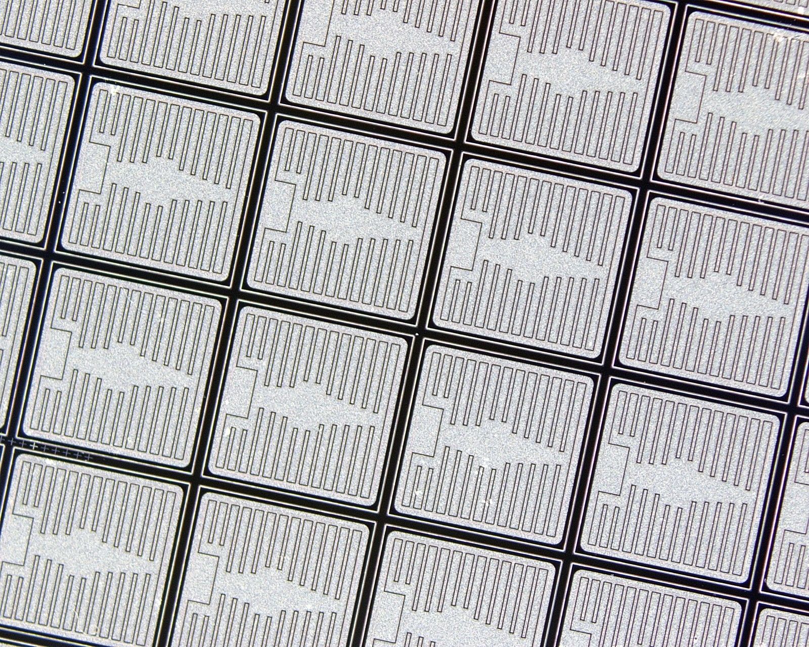
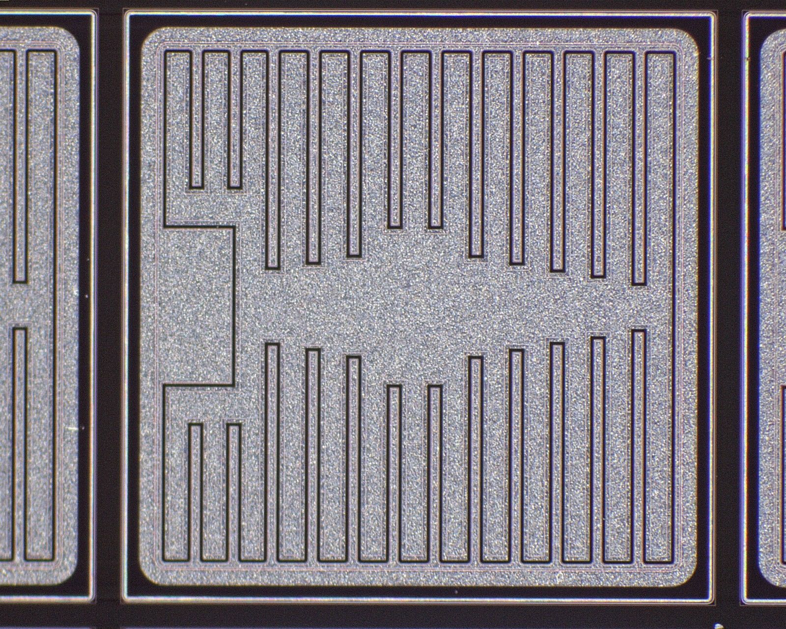
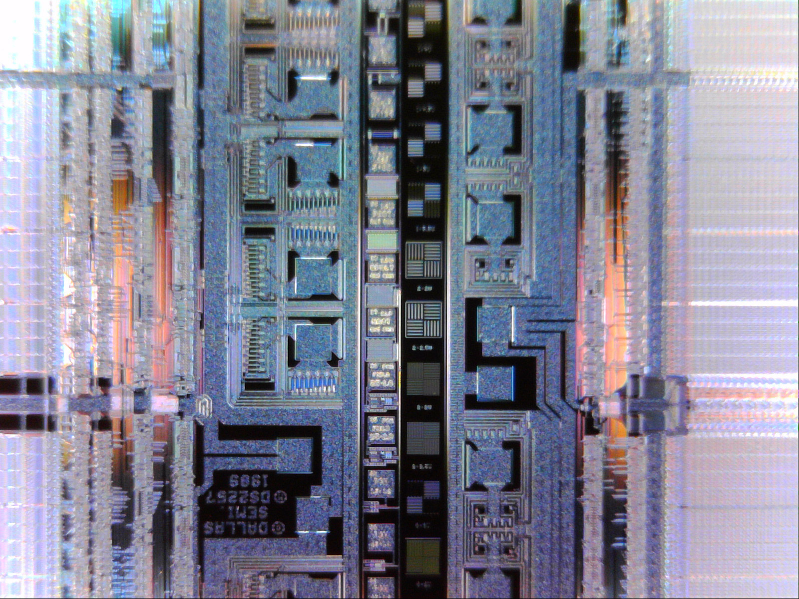
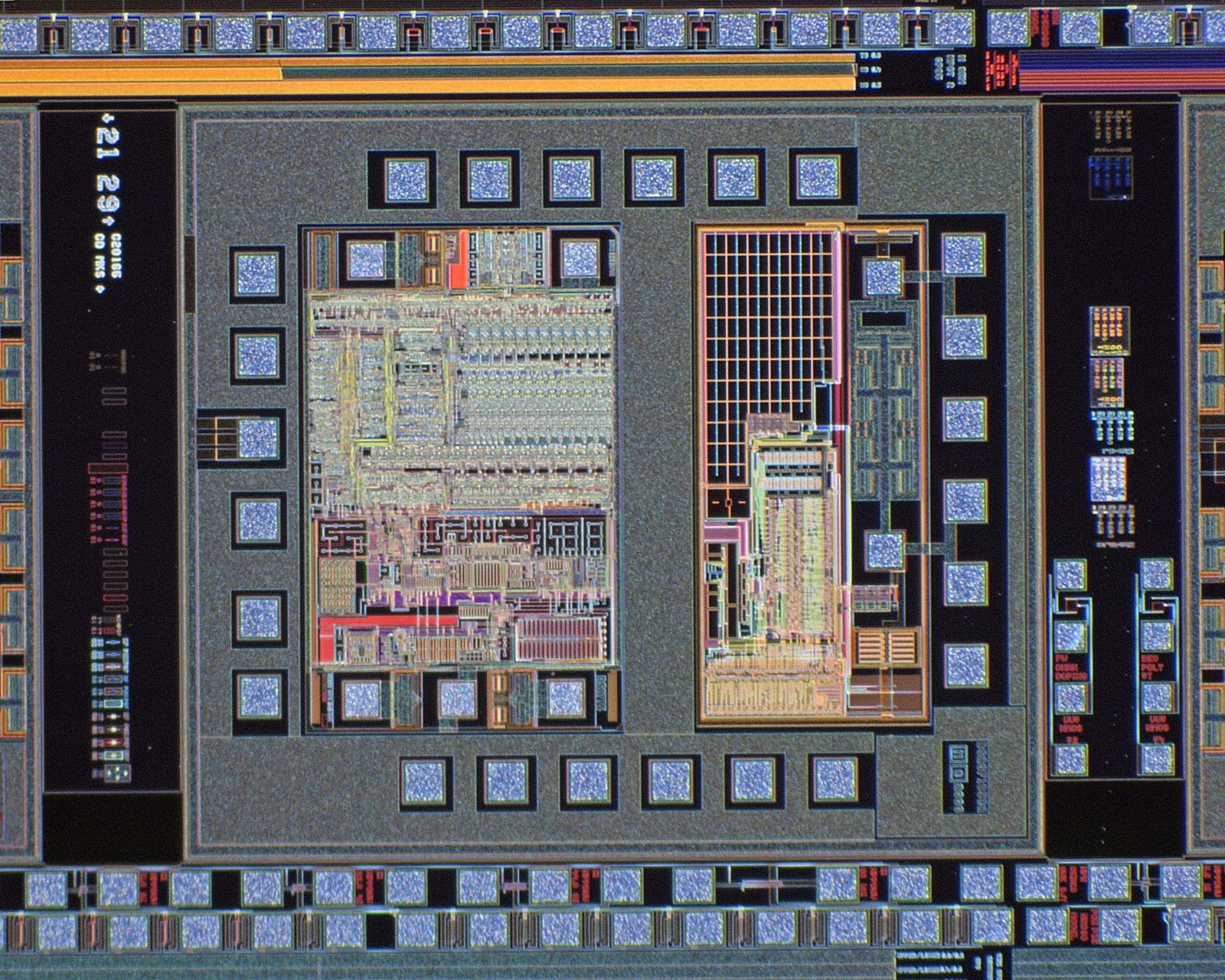
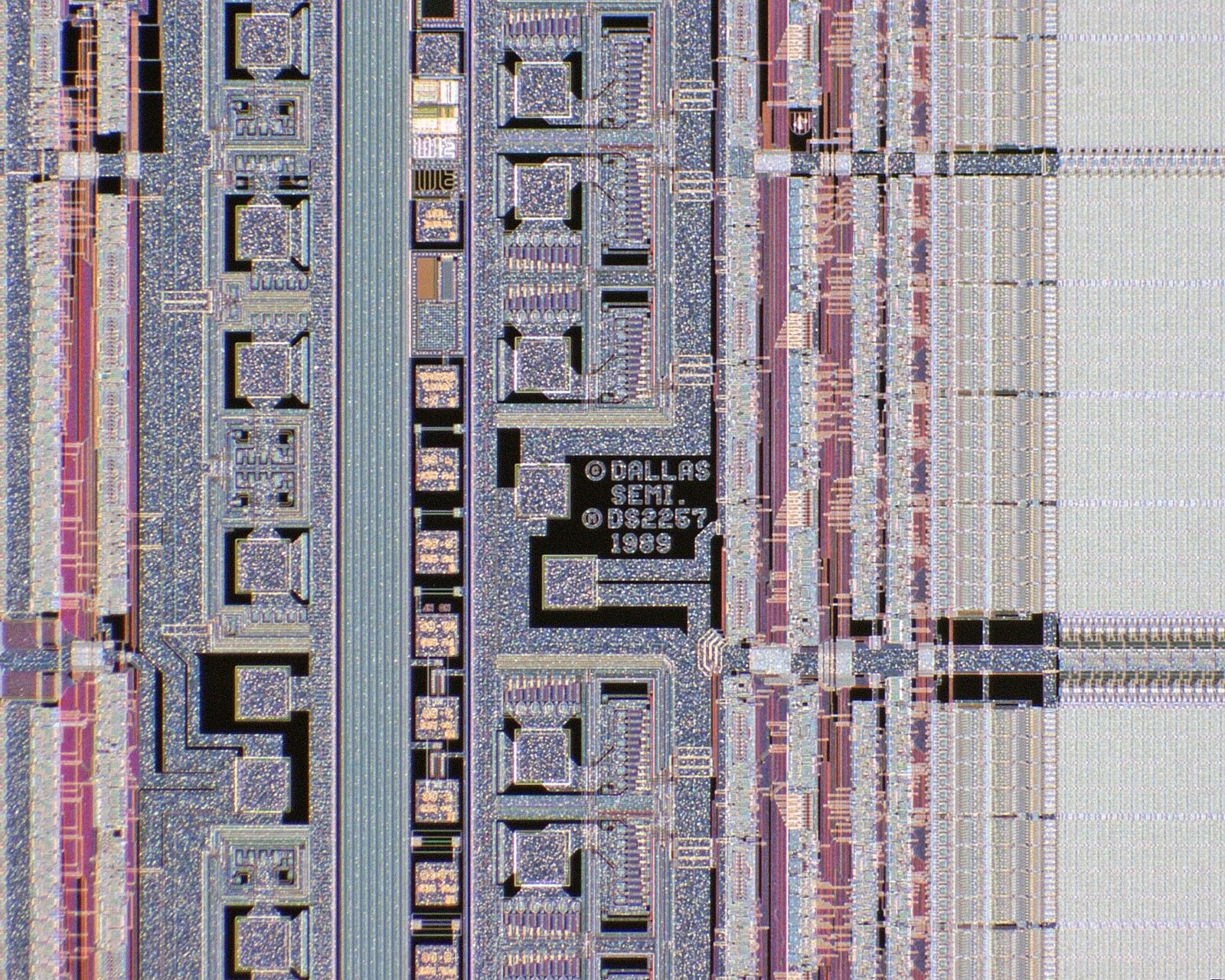
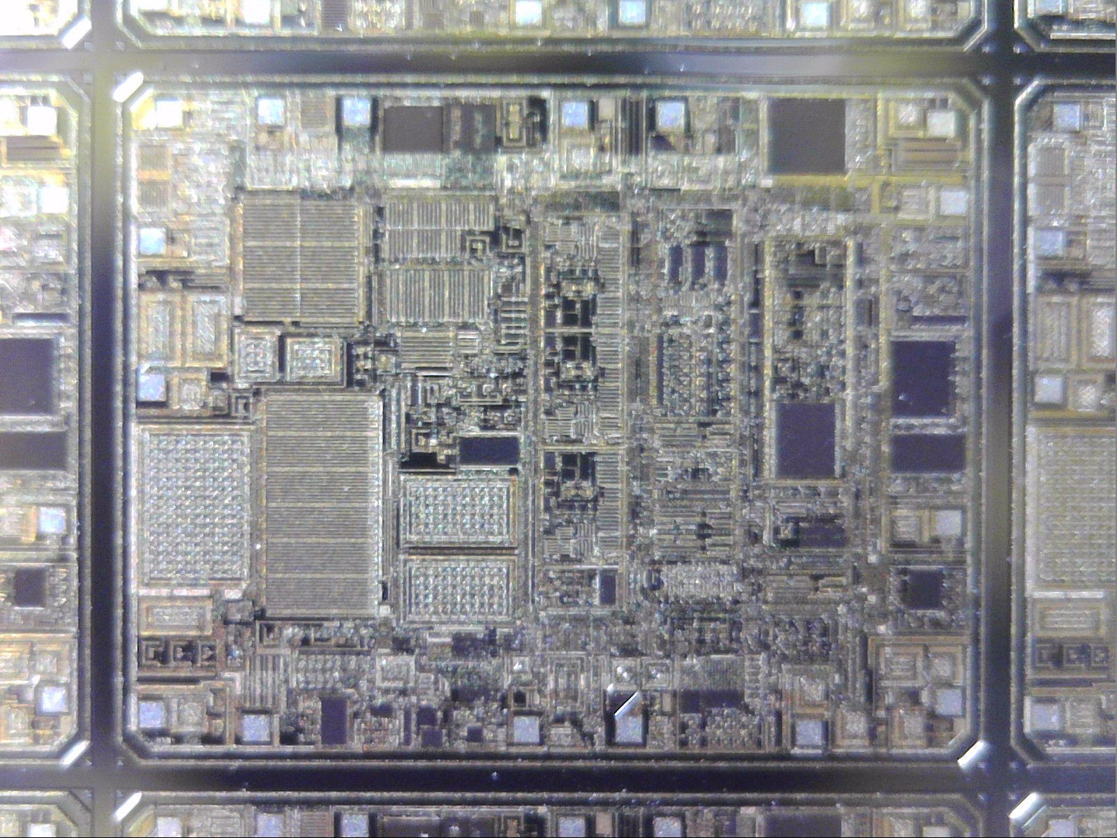
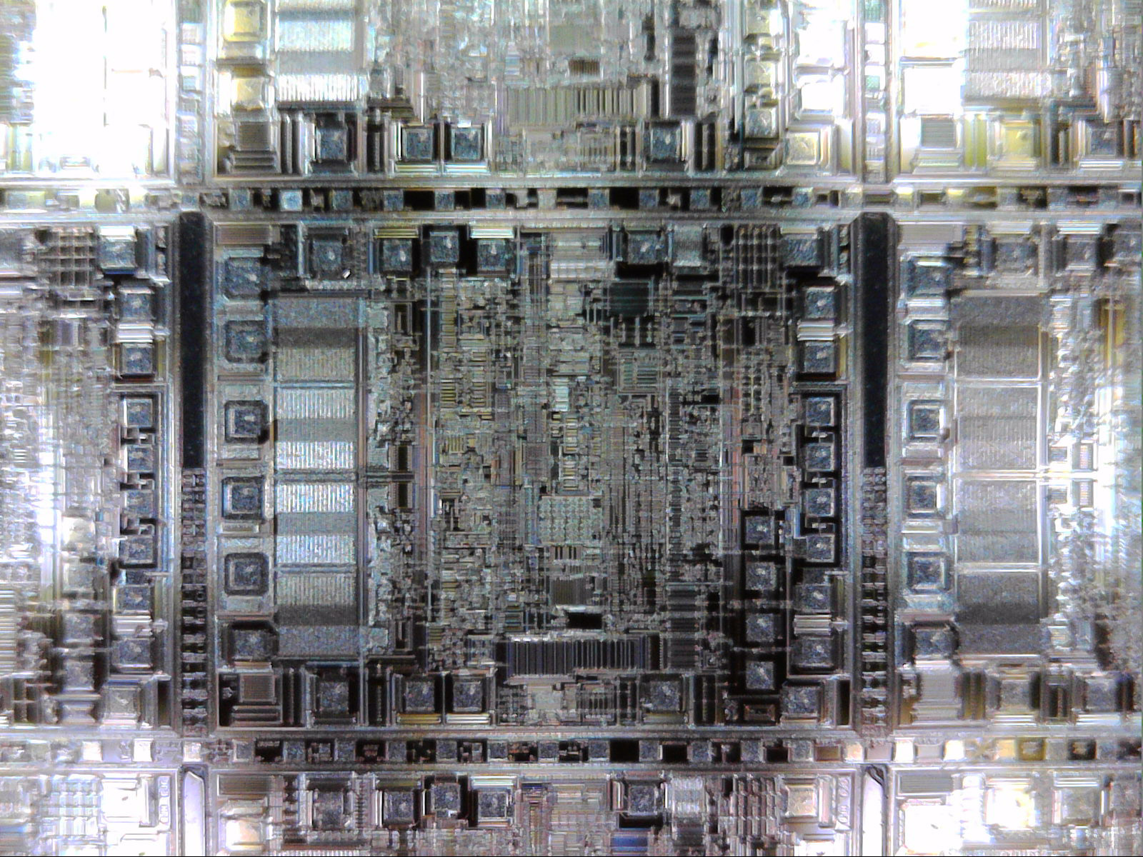
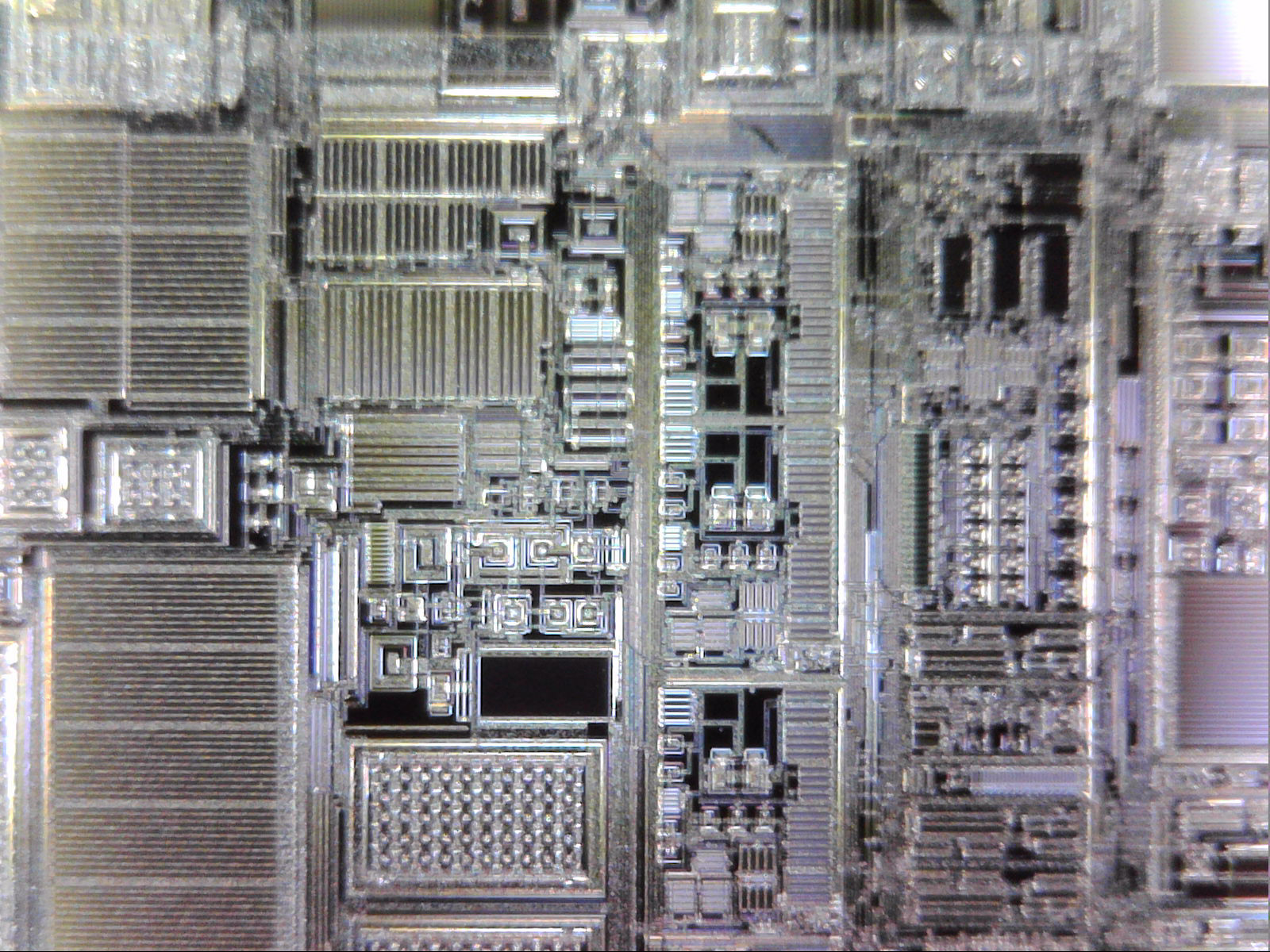
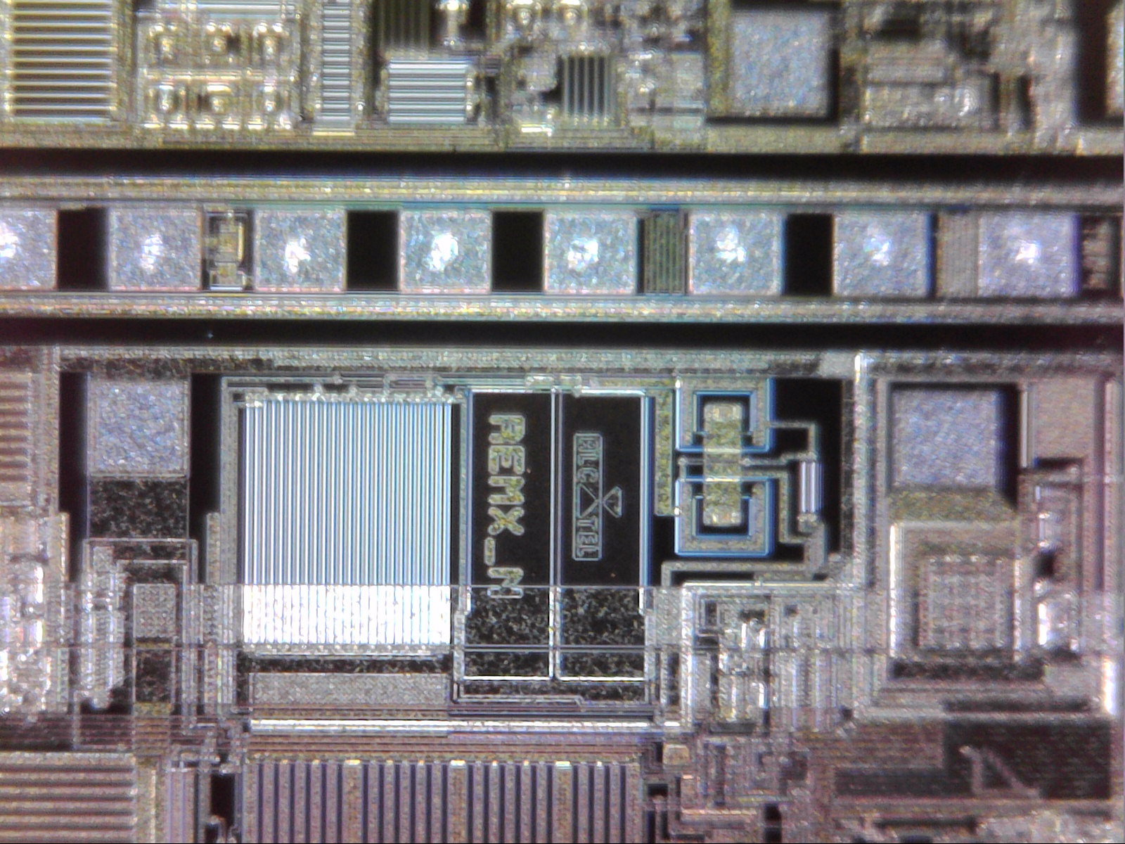
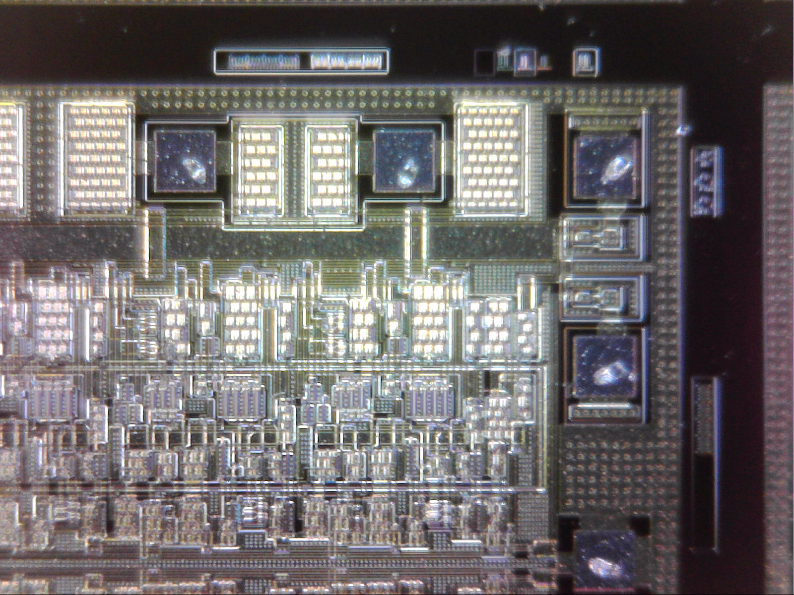
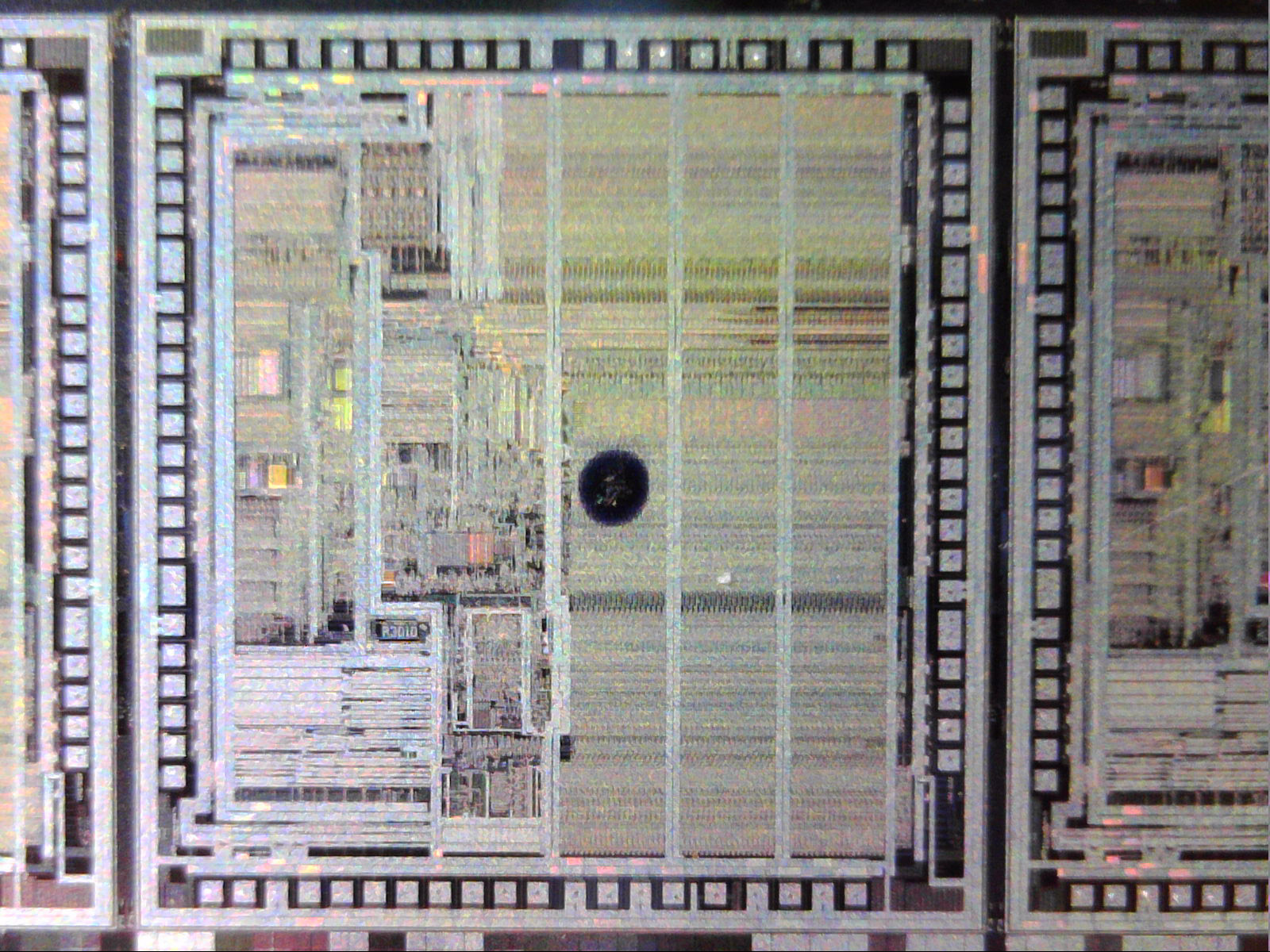
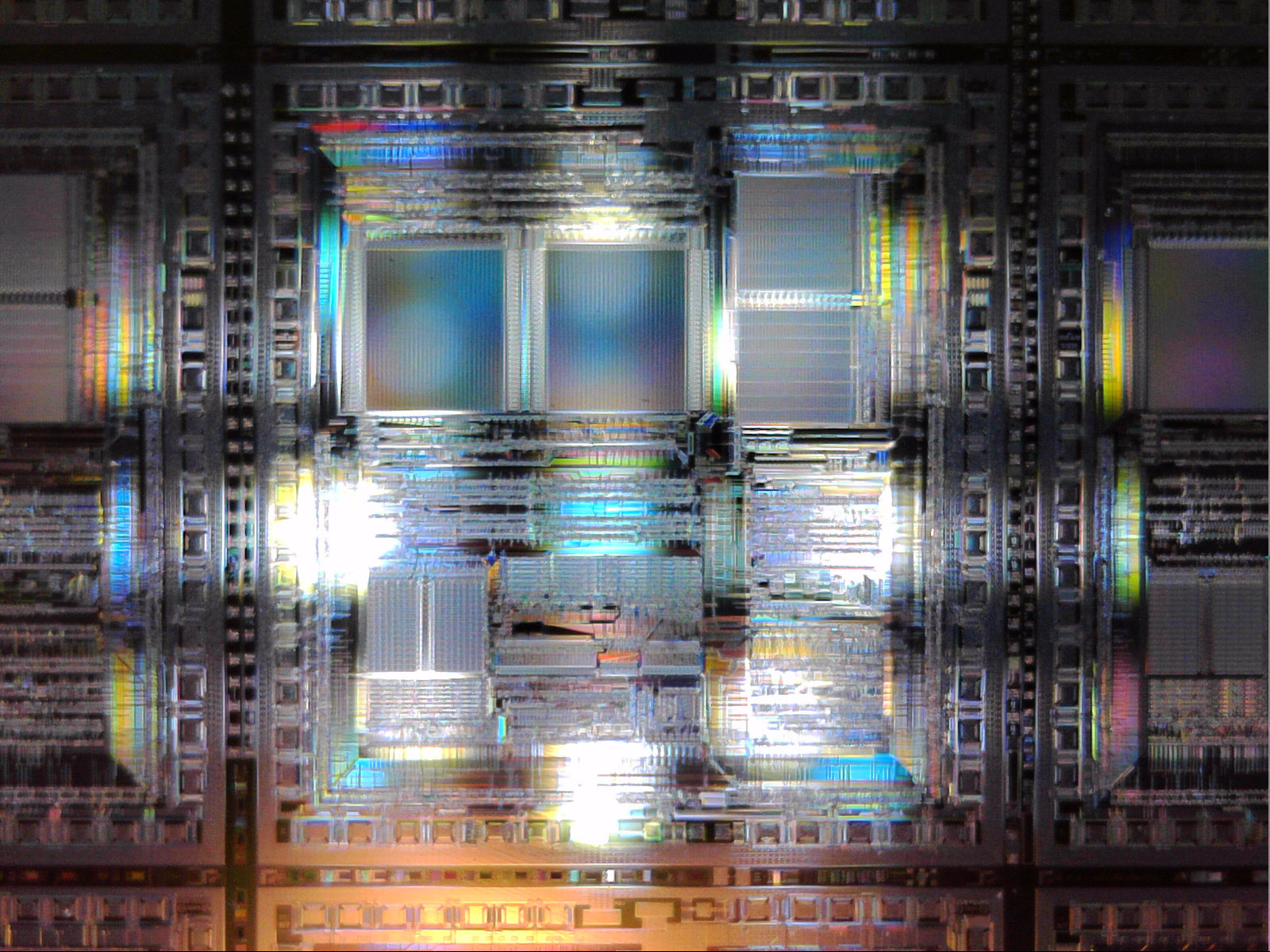
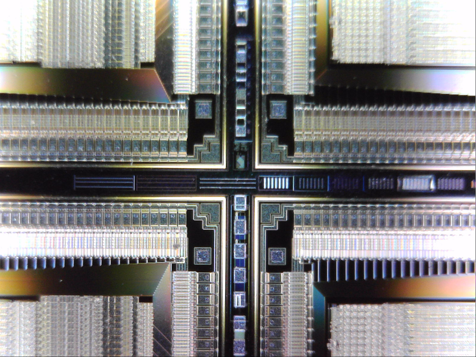
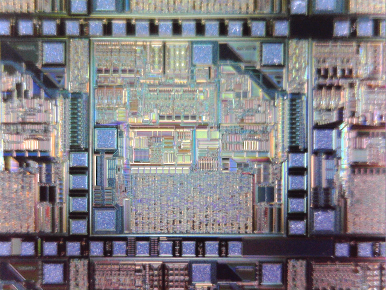
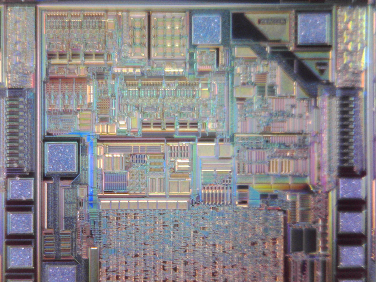
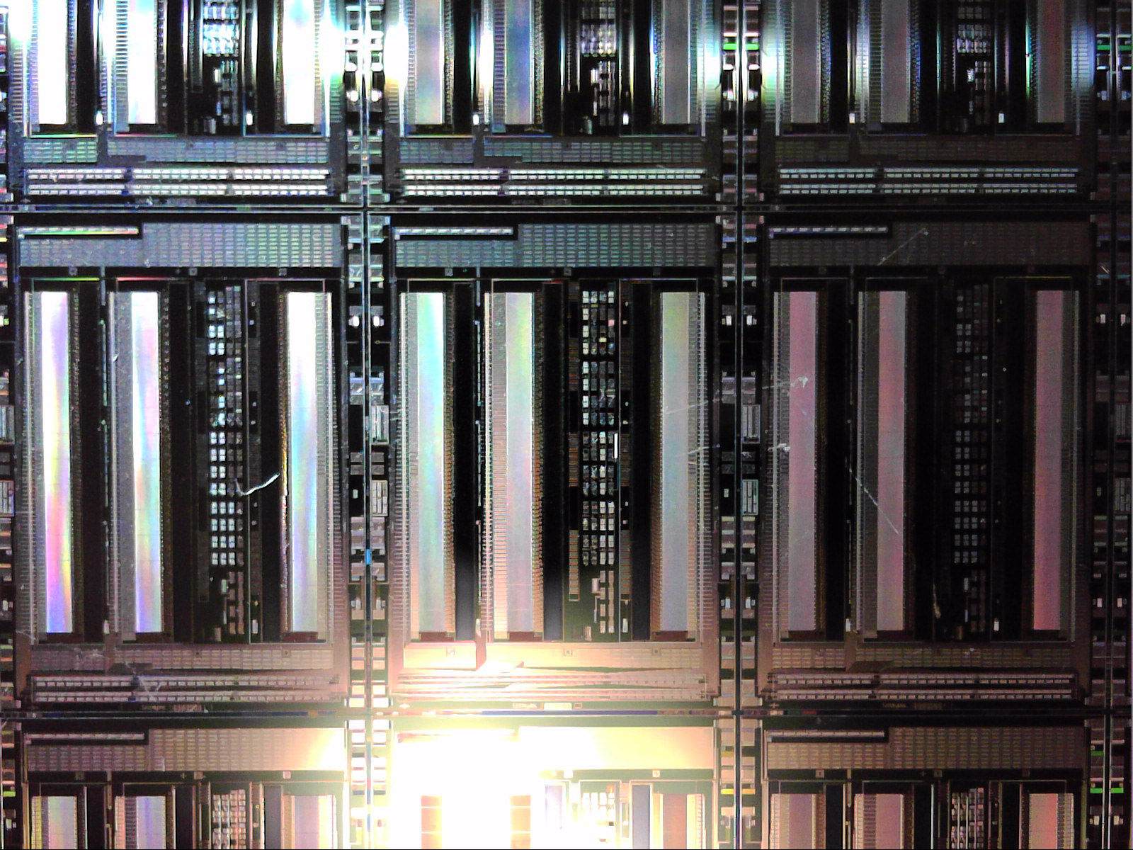
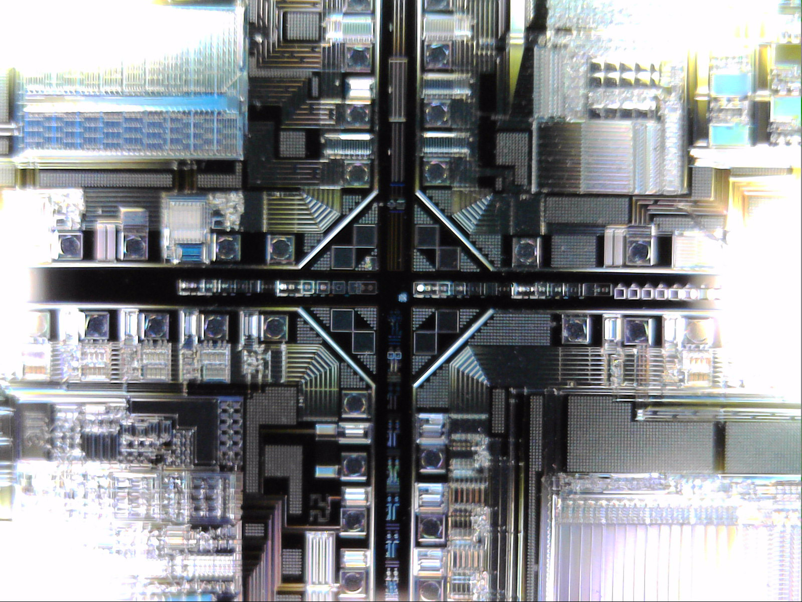
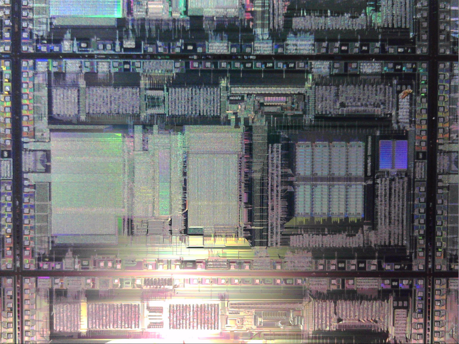
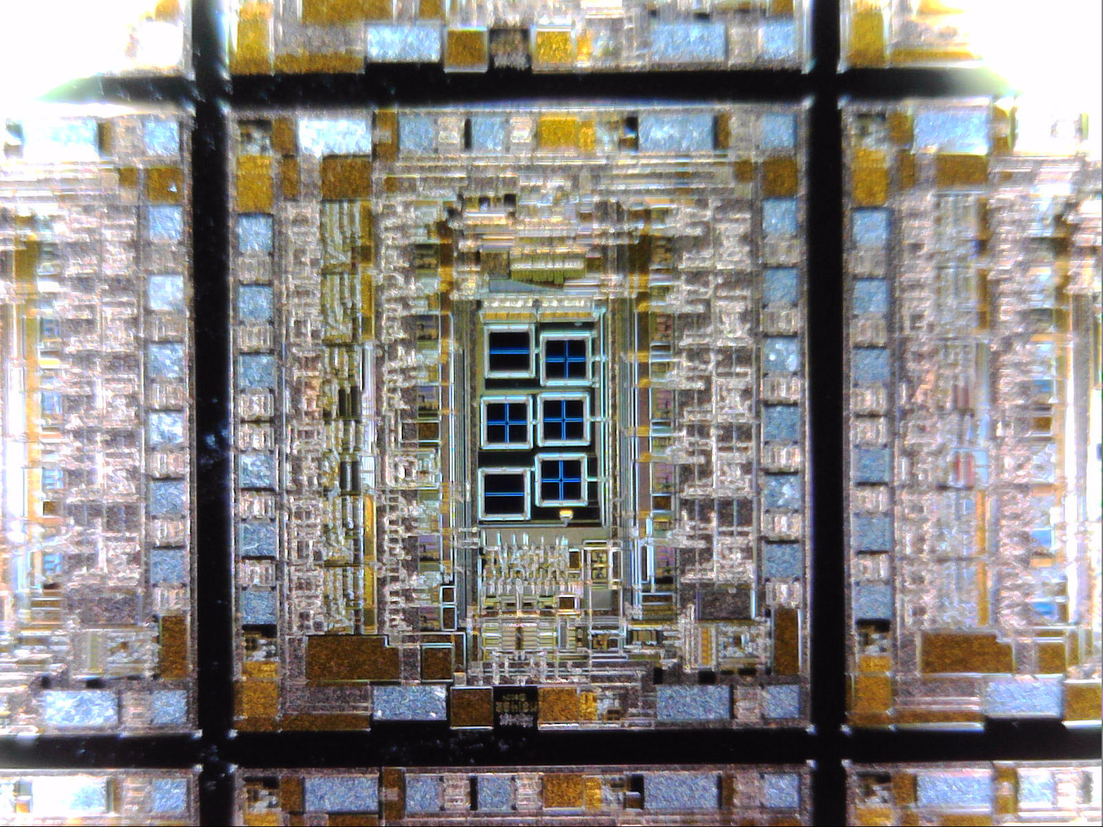
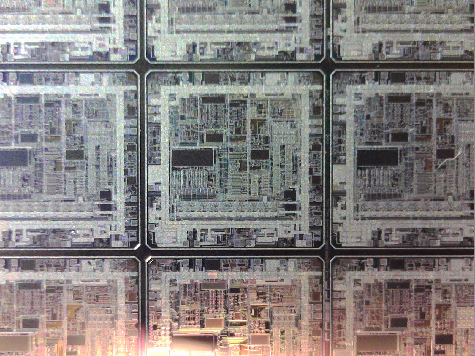
Finally, since I know some people love them, here’s some photos of the Silicon Wafers taken with a 500x digital microscope so you can see what they look like up close. The patterns vary widely depending on the wafer – memory tends to look like repeating structures, logic gates tend to look like a random mess, and sensors/anything analogue/test patterns tend to look like some abstract painting. I could swear that one of them has Silicon art of an OR-gate with one leg shorter to make it look more like the Star Trek logo, but it’s just slightly beyond the magnification limits of my microscope so I can’t photograph it. Most of these are from the wafers you see in this artwork, but there’s a few from other wafers I didn’t use.
For the 2018 Supanova pop culture convention in Brisbane, Australia I had the ridiculous idea to make three very similar costumes following three rules:
Internet memes
That are at least 15 years old
Involving a giant banana
I still can’t believe that I managed to get three costumes out of something so restrictive.
To go with this costume I made a red sound box to play music that I could dance to. That’s mostly what I want to write about on here, but let’s just get the costume photos out of the way first.
Friday’s costume: ring ring ring ring ring ring ring, BANANAPHONE!
Sunday’s costume: Rejected by Don Hertzfeldt’s My Spoon Is Too Big (which, by pure luck, was re-released in 1080p just two weeks before the convention)
“My Spoon is too big. My SPOON is TOO BIG!”
As you can no doubt tell, I spared no expense with these costumes.
The red sound box was one of those things that “should” have been easy, but because I used cheap Chinese parts & left it to the last minute, it became a giant cascade of one hack after another. The idea was to have a button that when pressed played a short piece of music to accompany that day’s costume variation. I wanted the front button to be super enticing so other people would want to press it, and nothing’s more enticing than a giant glowing red button. I eventually got there with everything, but it ended up way more complicated than I had anticipated.
The software on the box isn’t too complicated – press the button, music plays for a bit (just the first stanza). Press it again while it’s still running, it’ll play a little longer. The list of stanza stopping points was all pre-calculated per song. I’ll say right now, with anything like this it’s very important to consider how trolls could abuse what you’re building. In this case if someone ran up, pressed it a dozen times in quick succession then ran off, it only extended the music by at most one stanza beyond what’s currently playing – if you wanted to keep the music going you had to stay there and keep on pressing it as each stanza plays. And yes, many people tried doing that – much to their frustration when it didn’t work.
Here’s a numbered photo of the box’s innards, showing that copious quantities of hot glue & electrical tape are totally valid mounting & insulating techniques.
1) Arduino Nano 168p, 2) 5V relay board, 3) Red button light & microswitch, 4) Capacitors, 5) USB power bank, 6) Speaker, 7) MP3 board
Hacks & Slashes
Now for some of those hacks I mentioned:
The cheap Chinese Arduino Nano’s (#1) that I had bought were supposed to be based on the ATmega328P chip, however when I plugged them in they were actually using the ATmega168P. The 168 has only 1024 bytes of RAM instead of 2048, and that’s not enough to read data off a microSD card & send it to an MP3 shield for playback. This meant I had to use a different music shield with its own on-board microSD card that accepts play/stop control commands. I probably should’ve bought the right Arduino instead, but hindsight & all that.
The second cheapo MP3 shield I tried had no on-board amplifier. I bought a cheap eBay amplifier for it, but for whatever reason the amplified sound quality was atrocious – worse than a fast food drive-through speaker. So I had to change to yet another music board (#7), this one even simpler – apply power, it played the first song on its microSD card, and it had manual buttons I could tap into to control it beyond that.
This worked great on a breadboard on my desk, but when all installed into the box there was too much electrical interference – likely because the speaker’s (#6) magnetic coil was right below the music board (#7). I could start the board, and control playback when it was playing music very quietly, but I lost the ability to control it or even stop it when playing music above a certain volume. Given I was running out of time and all I really needed was to just start & stop the music, I decided to use the sledge hammer approach. By which I mean I added a 5V relay board (#2) to manually supply & cut all power to the music board (#7) to control it that way instead. Insert an “I’m done asking nicely” reference here.
This worked, but only intermittently – the relay’s (#2) inrush current was large enough to cause the Arduino to sometimes reset from the voltage sag, particularly when running off the battery and not my bench power supply. So, I added a ceramic & electrolytic capacitor that I had lying around (#4), and this fixed the voltage droop problem.
…But it created another problem. The USB power bank (#5) I was using couldn’t handle the huge inrush current required to charge up the capacitors when you first turned it on. Rather than do something sensible like swap batteries or reduce the capacitor values, I wired them up so the USB bank went straight to the Arduino’s USB point (#1) but the capacitors were connected via the Arduino’s pins, in effect using the thin traces on my knock-off Arduino as inrush current limiters to the capacitors. This is what peak hack looks like.
The USB power bank (#5) had another issue – since this was a power bank not a power supply, it was designed for charging things, not powering devices. As such, it automatically turned off if it thought the device it was connected to was fully charged. The clever hack to get around this was to reduce the value of the resistor to the glowing red button (#3), making it use more current & shine brighter, and altering the button’s pulsing pattern. This was enough to trick the USB power bank into staying on. Remember folks, if it’s a silly hack but it works, it’s not silly.
At the convention centre the button kept on randomly triggering. Experienced cosplayers know that it’s always a good idea to shield, isolate & over-build anything electronic on your cosplay – the Brisbane Convention & Exhibition Centre main hall is well known as having a lot of stray RF noise inside it. I ended up modifying the code multiple times to incrementally harden it. I ended up adding my own external pullup/pulldown resistors around the place as I didn’t trust my knockoff boards to actually have them, I switched from a digital input pin to an analogue input pin for the button, I required reading a value of at least 992 out of 1023 from the button’s pin (aka 4.85V or higher), for 200ms straight without dipping for even a single moment, to trigger the music. This still resulted in a random trigger every couple of hours. Dat RF noise.
Finally, hot gluing the speaker (#6) in place introduced a lot of reverb from mounting it by a mostly-solid method to the case’s fixed plastic. A sheet of ~1cm thick EVA foam was used as a decoupling spacer between the speaker & the case, and this solved all the bad audio quality issues.
If I had one piece of advice I learned from this project, it’s that knock-off parts from China can get you by if you’re on a budget or while you’re testing things, but for the final version I absolutely recommend purchasing the genuine products. This project would’ve taken me a fraction of the time it did if I had just spent a little extra for quality parts in the beginning.
(If I had a second piece of advice, it would be to set yourself a deadline well before something’s due. That way you’re not stuck hacking things together at the last minute from whatever you’ve got on hand plus what you can buy locally at exorbitant prices… But we both know neither you nor I are ever gonna actually do that one)
This audio box’s going to be disassembled shortly, because I need some of its parts for another project (and it also served as a semi prototype of yet another underway project… I have too many things in progress).
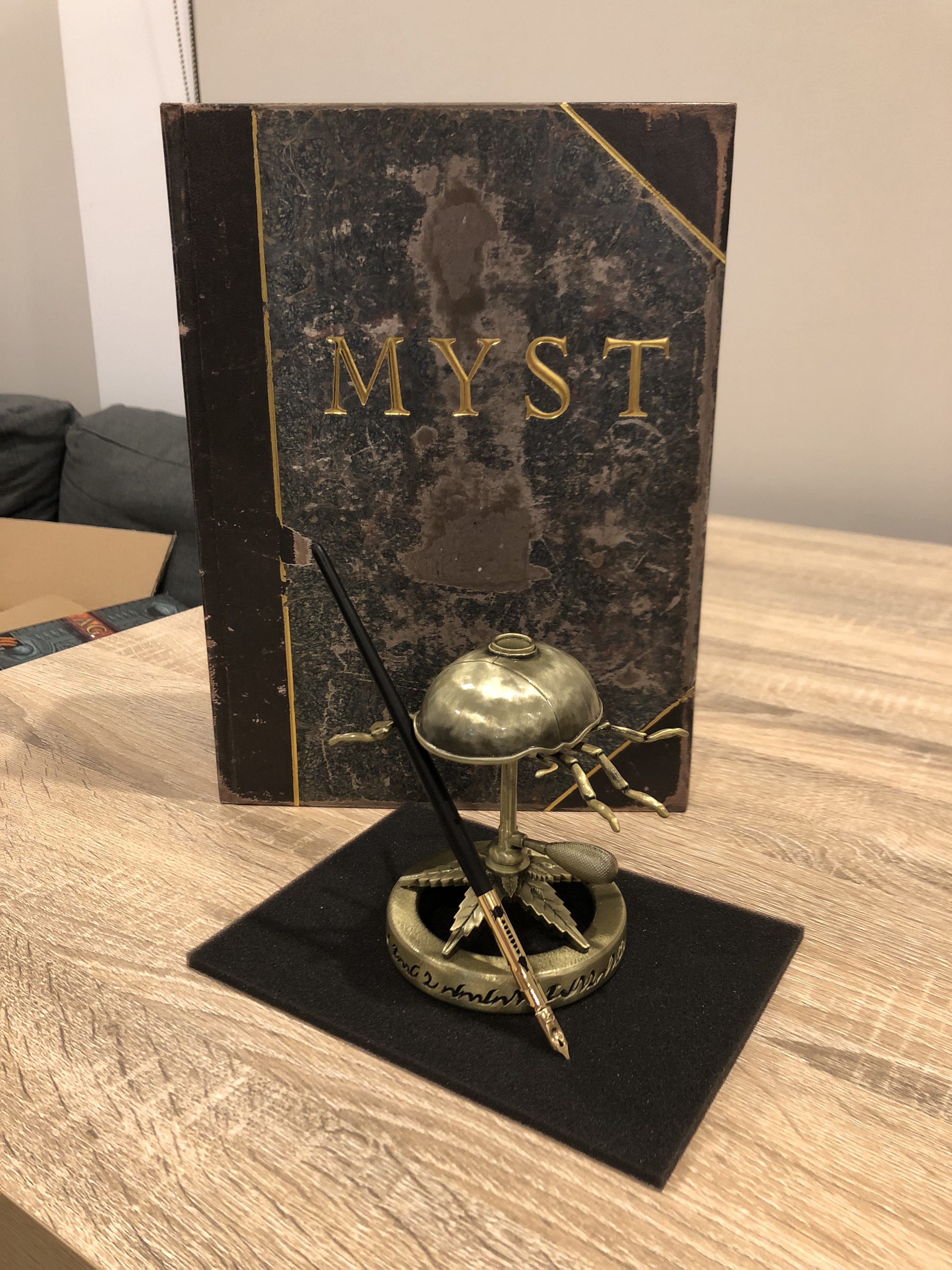
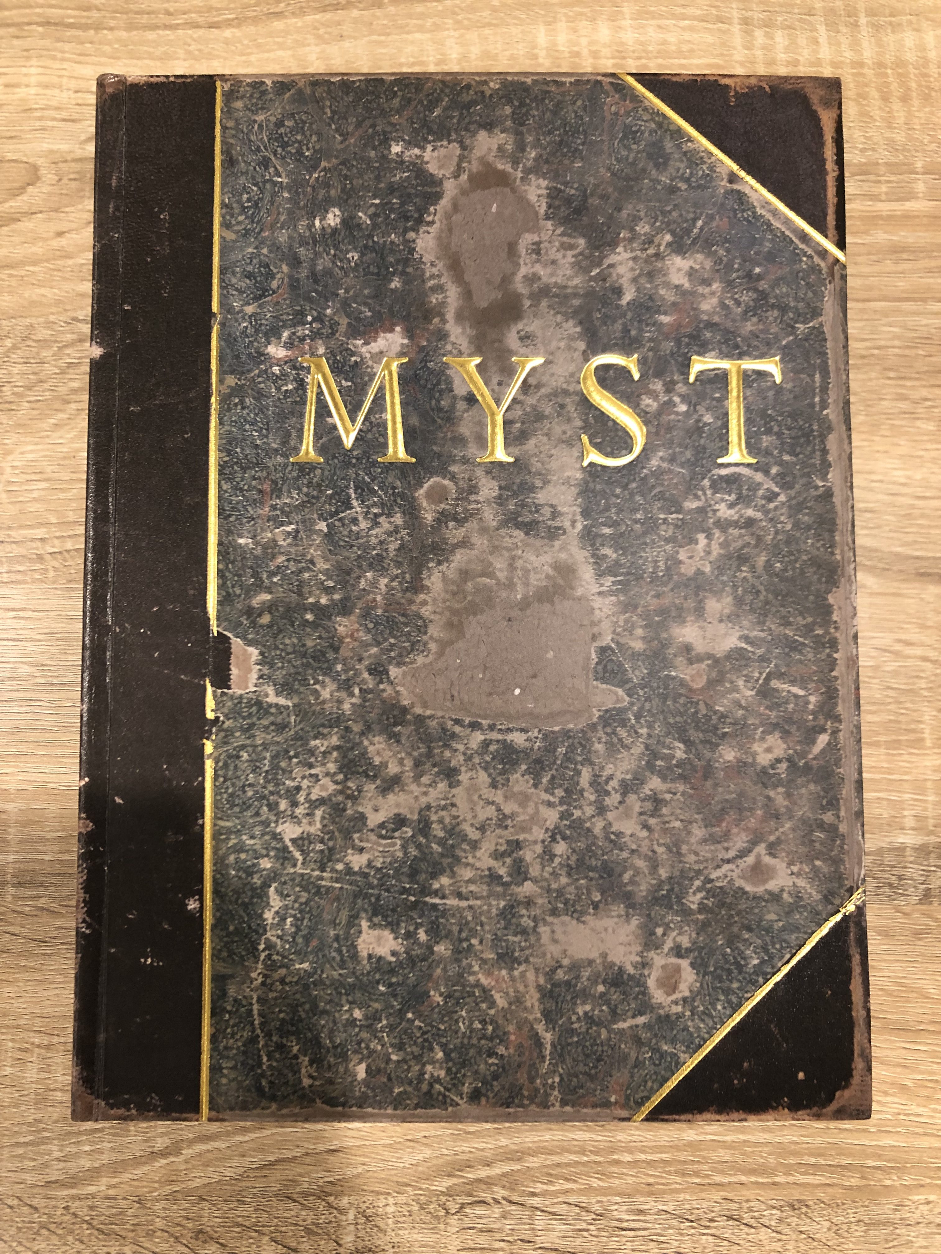
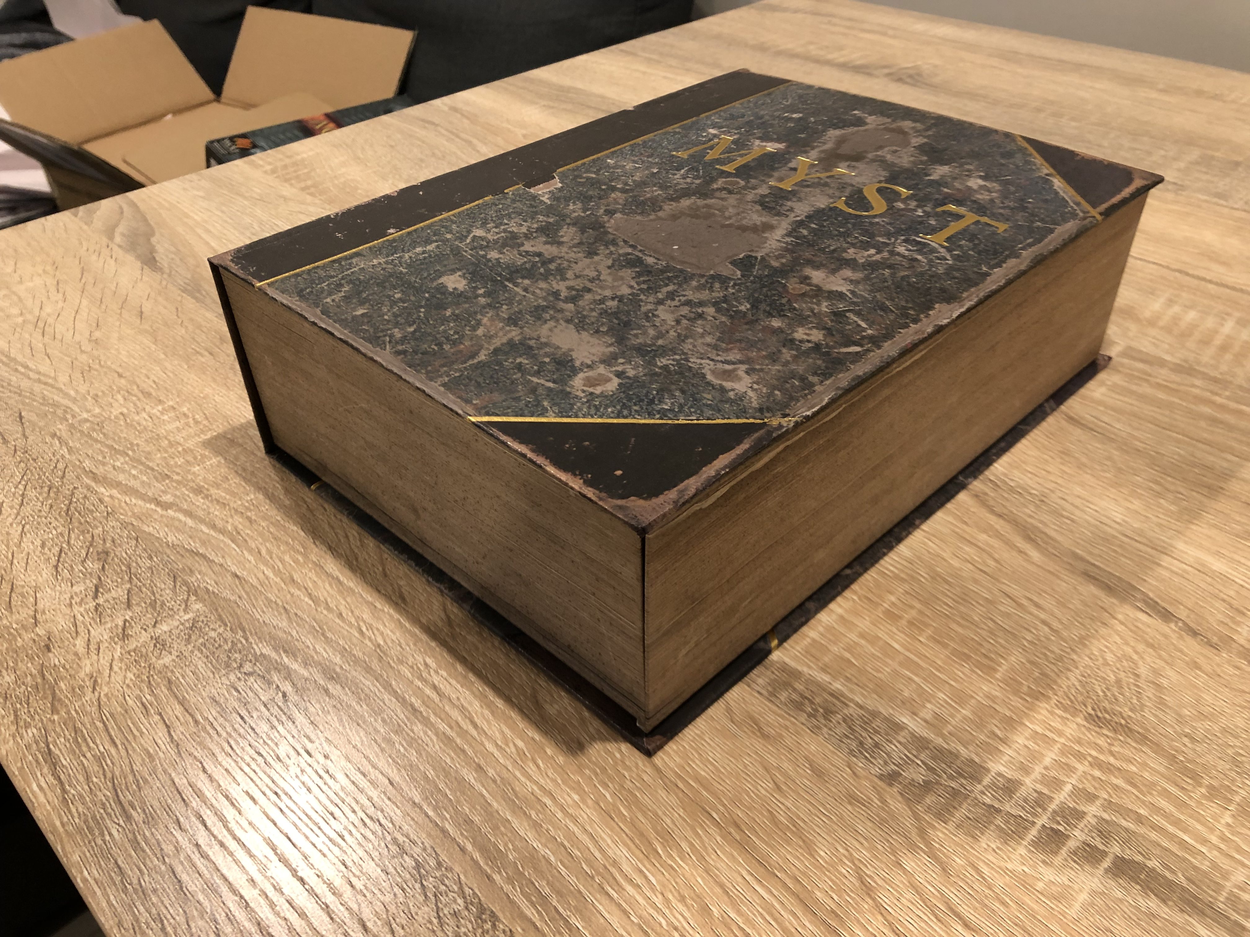
The #Myst25 Myst 25th Anniversary Kickstarter rewards are finally getting sent out! Since I got lucky & somehow managed to be one of the first in the world to gain access to one, I thought I’d post some photos & a bit of a review of them. Particularly since I’m the guy who made the real Myst book replica, so I’m probably the non-Cyan-employee who has spent the highest number of hours obsessing over what this book is supposed to look like. Fair warning, this post is gonna be a bit long & a bit image-heavy, but that’s probably what you’re looking for anyway!
The Myst Book
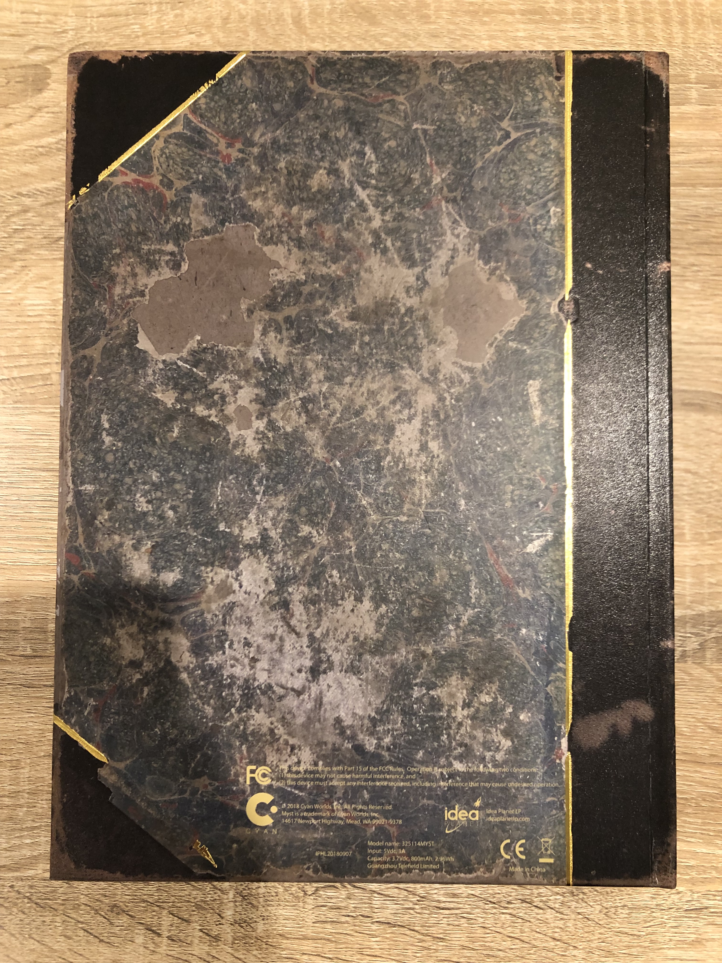
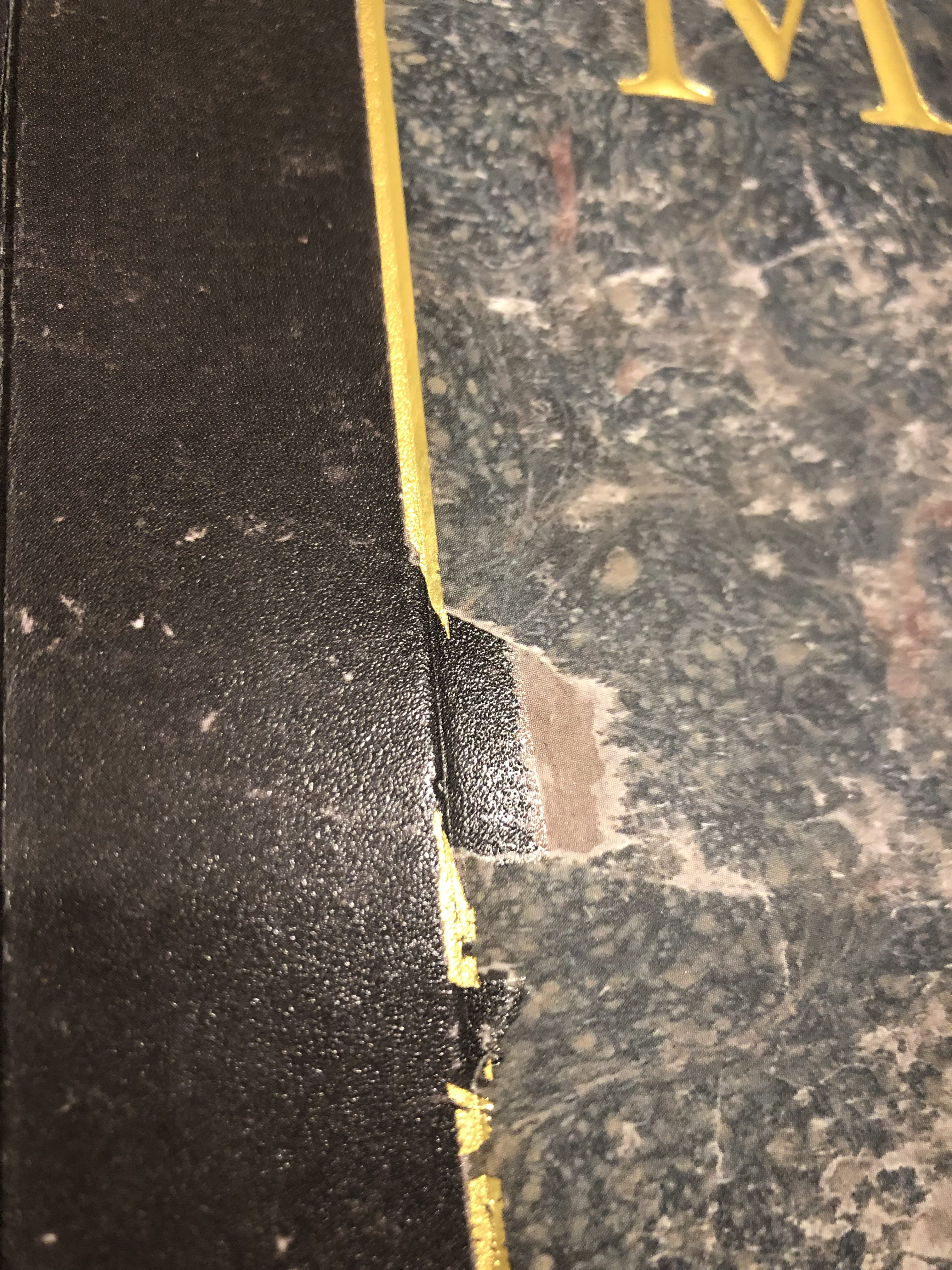
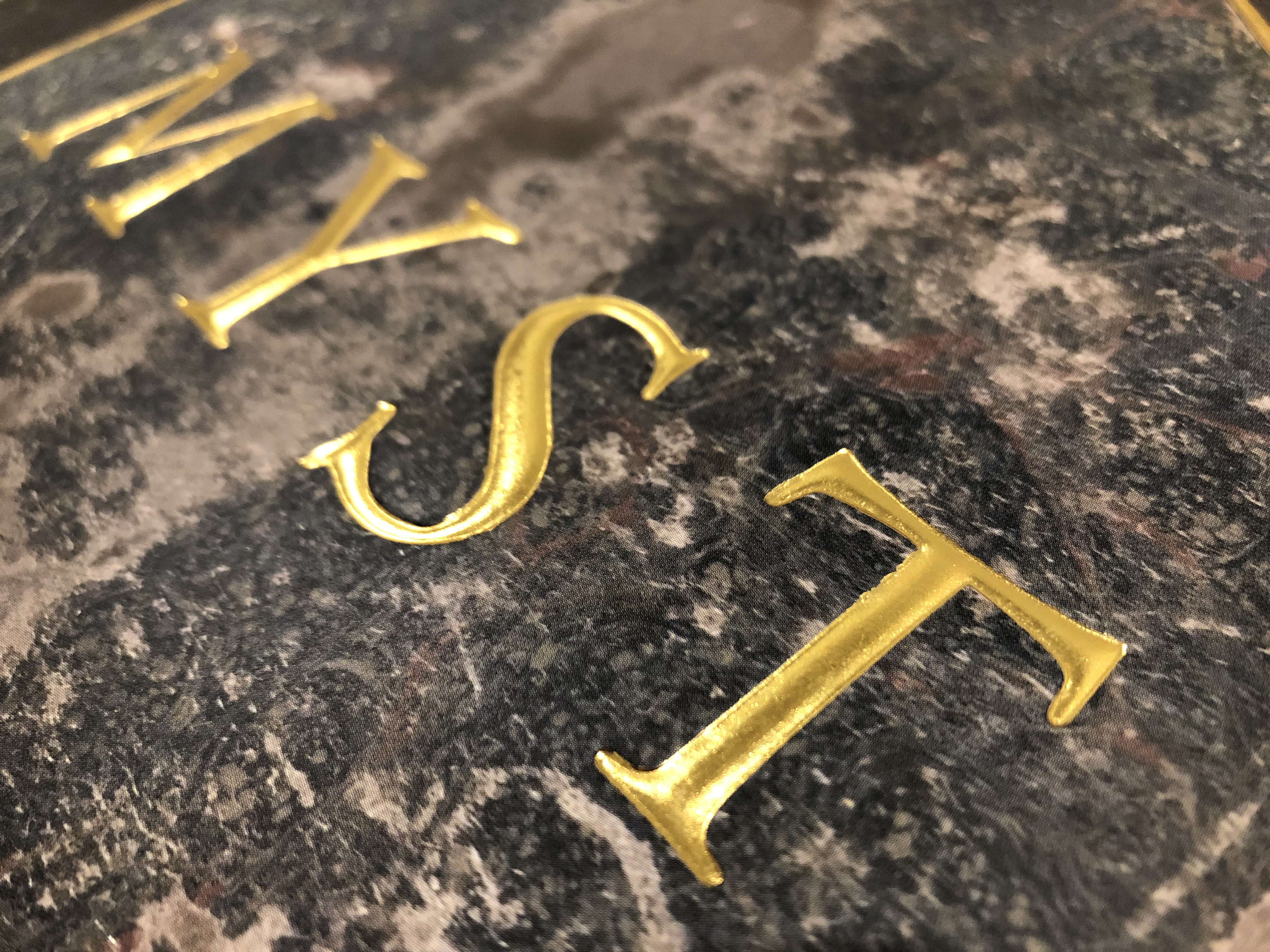
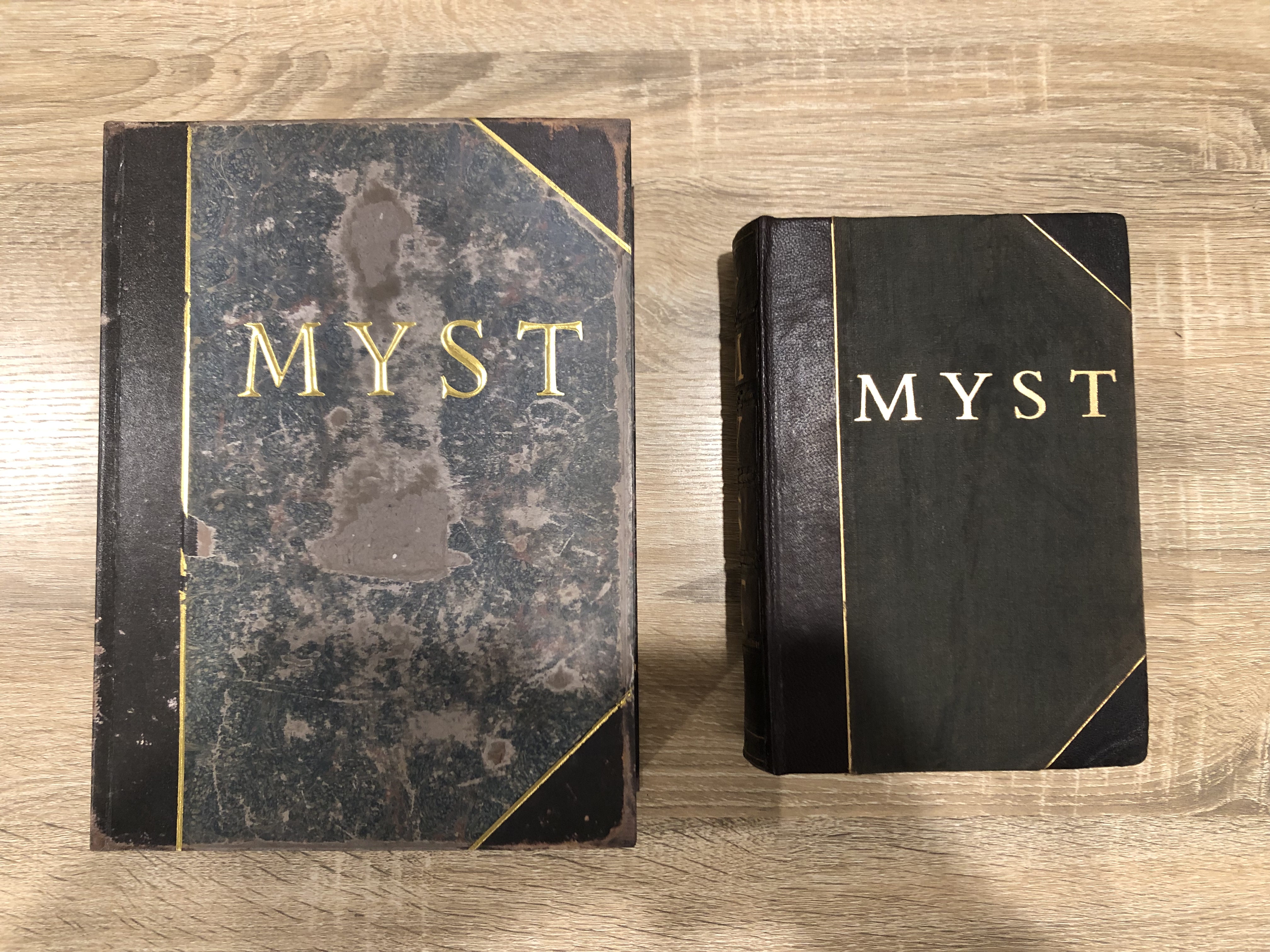
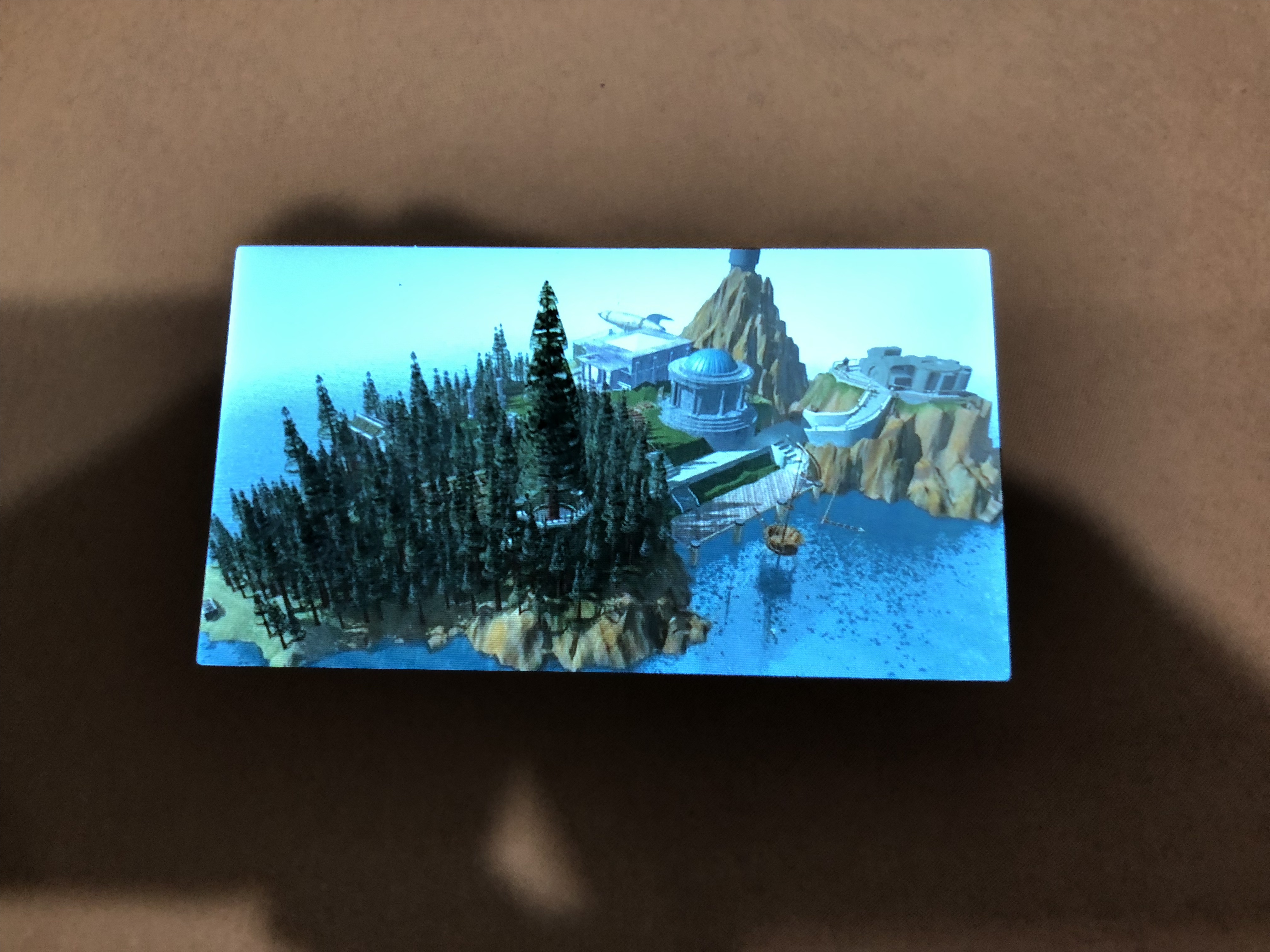
It seems to be pretty well made. It’s bigger than mine/Cyan’s book, but I kindof expected that might be required to make the ink well parts fit. To try and compensate for this the covers are thinner than the original, which I think is a fair compromise. I need to point out that the outside cover has been made with a lot more detail than is immediately obvious – this thing’s been constructed in enough layers to impress an ogre. There’s the plain bare cardboard, which is most easily visible through the infamous damage notch on the left. Then there’s the dark brown leather/cloth layer on the left side and on the two corner triangles, which has had both a bit of a shine and a rough surface added to it that roughly matches the shine & feel on the original book. On top of this is the main central texture as a normal paper print, and on top of that are sections that have been raised/embossed, and on top of that are sections that have been gilded. Some of the damage marks on the book aren’t just in the image’s print but are actual cut-out holes where one layer gives way to show a lower layer, which I think is all pretty darned cool. This applies to both the spine and the back of the book too – speaking of, the back of the book is what the back of Cyan’s actual book looks like; for once it isn’t just a mirror of the front texture like it is in all the games!
Speaking of just the front texture, it’s a bit different to what was shown in the Kickstarter. The Kickstarter version was a blend between Cyan’s actual well-worn physical prop book and my own replica, whereas this final version is mostly like Cyan’s one (and for what it’s worth my one was supposed to be my interpretation of what the Myst book might’ve looked like when “brand new”, mostly because luck meant I found a copy of the right book in near-perfect condition, which is why it had no damage). There’s a couple design points similar to mine – for instance the font used for the raising/gilding looks like it’s been modified a little from the original MYST font to straighten the serifs a little, the same as I did, which makes it look better when embossed or raised. The main image is also darker than Cyan’s actual physical book, and has had more damage added to it than Cyan’s book actually has, particularly around the edges. It’s worth mentioning here that back in 1993 Cyan did scan their physical prop book to use as a texture, however back then they modified that image so it had less damage in-game vs what it had in real life. This makes one more version of what this book is supposed to look like, and when you add in how it looked during Myst 5 I think I’ve lost track of how many different versions we’re up to now. 😛
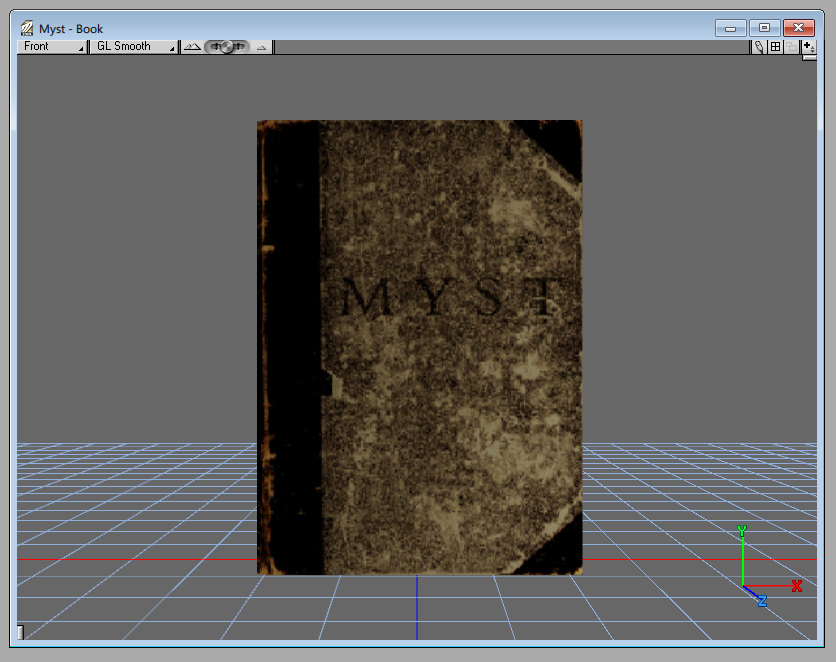
The original 1993 version of the Myst book 3D model as shown in Strata
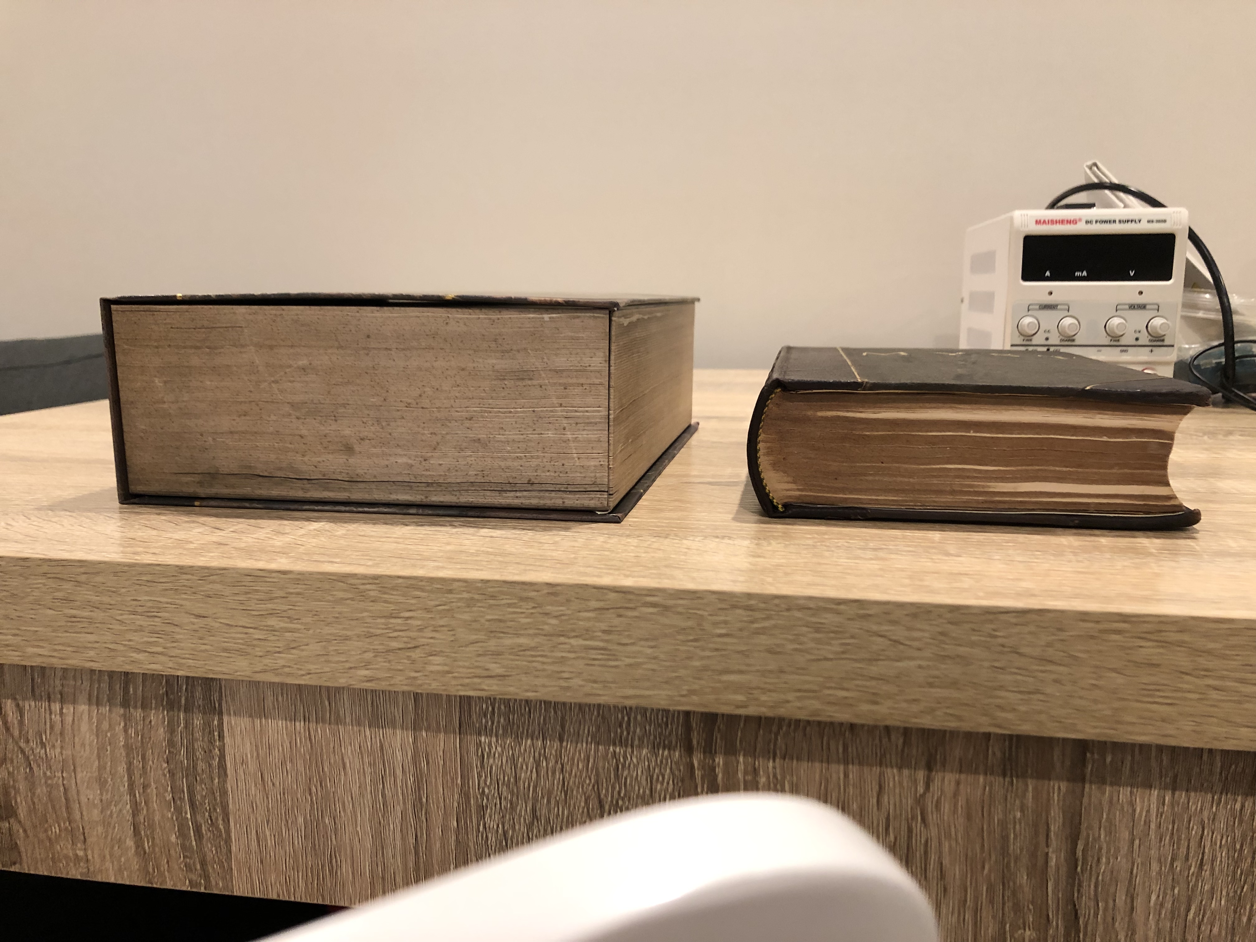
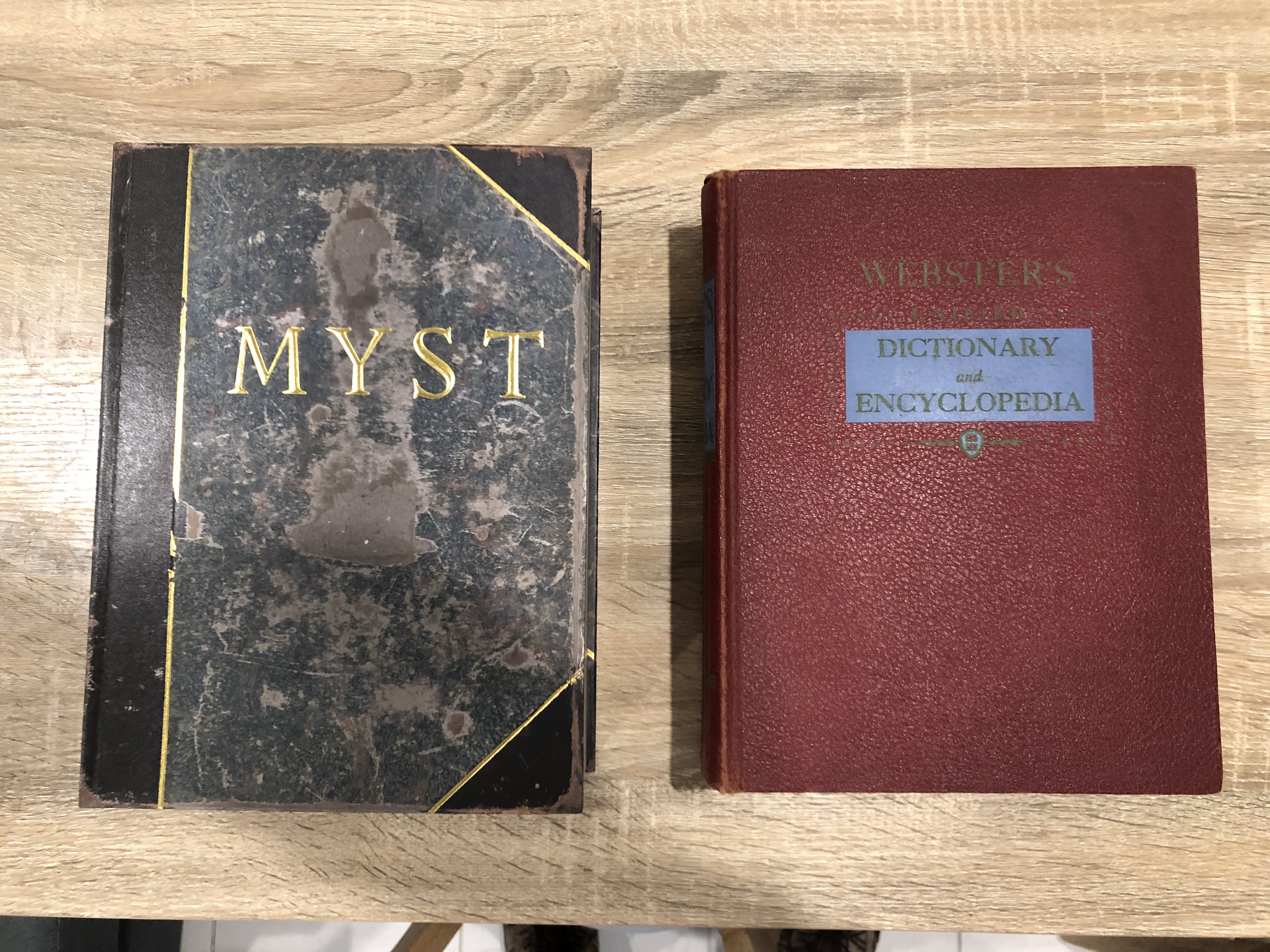
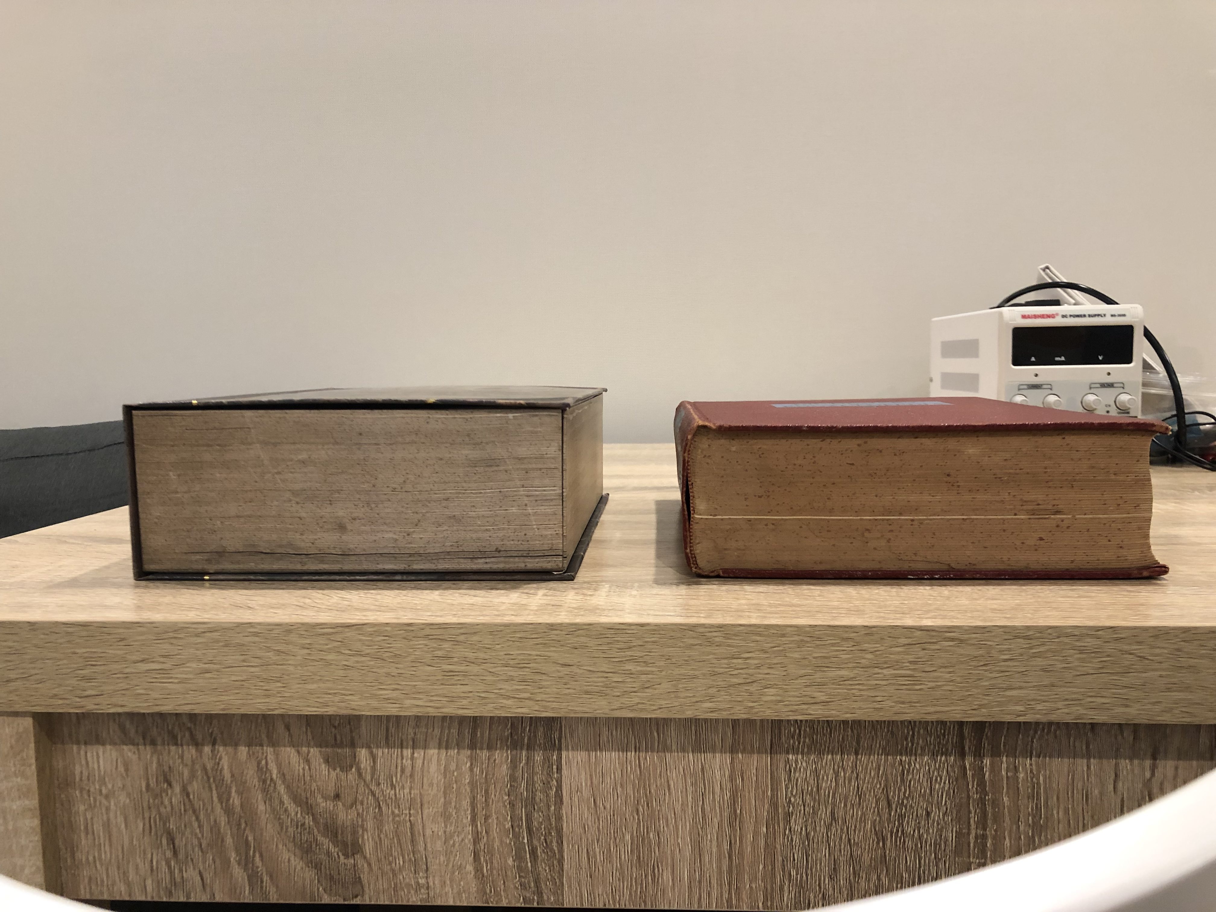
Because I knew people would ask, I took a few photos comparing the Kickstarter Myst book to my replica Myst book so you can see the size difference. I also took a few photos comparing it to the original book Cyan used as the Riven descriptive book (The 1954 printing of the 1951 edition Webster’s Unified Dictionary & Encyclopedia if you’re curious). Turns out it’s much closer in size to Riven’s descriptive book than Myst’s linking book!
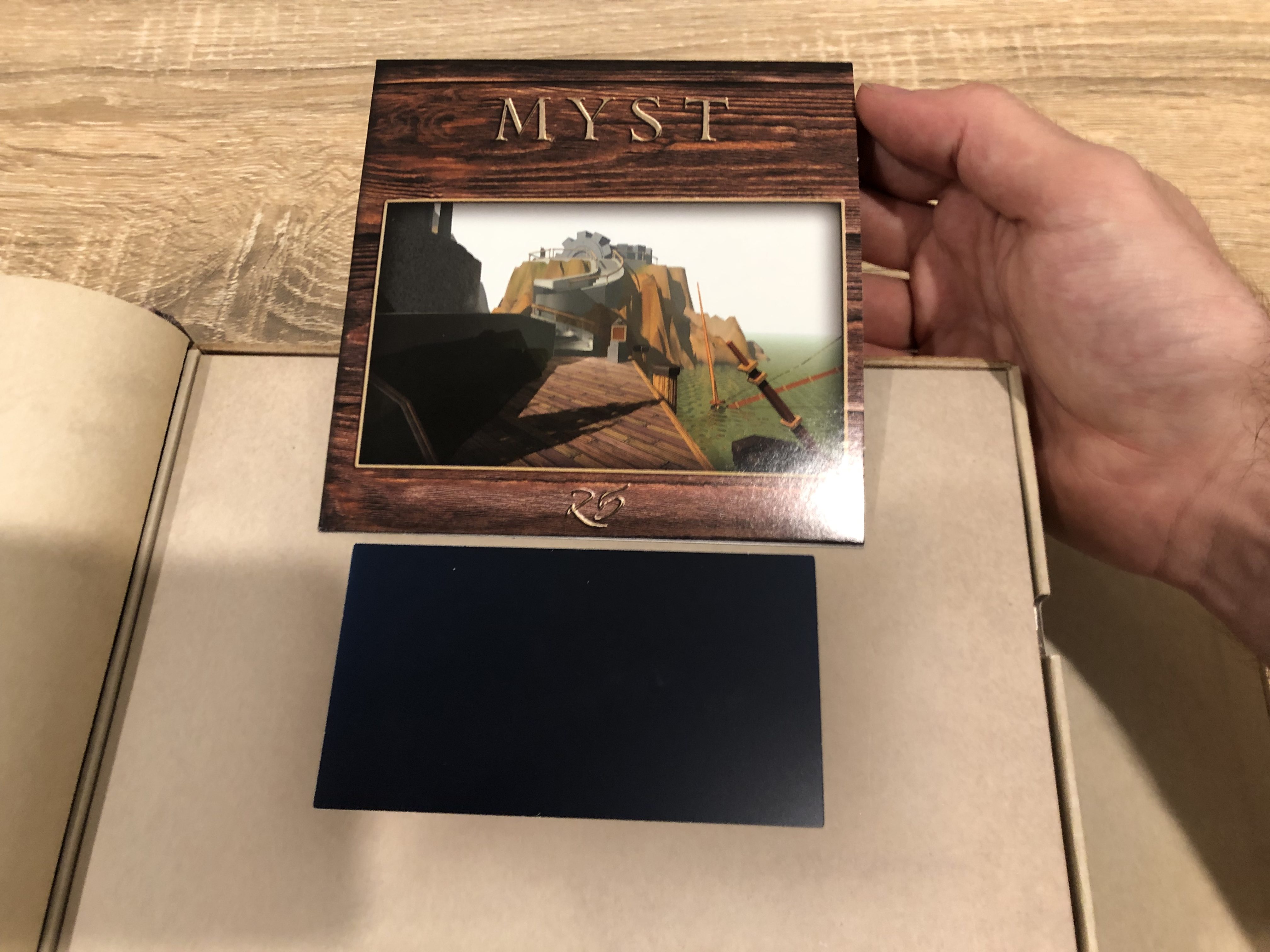
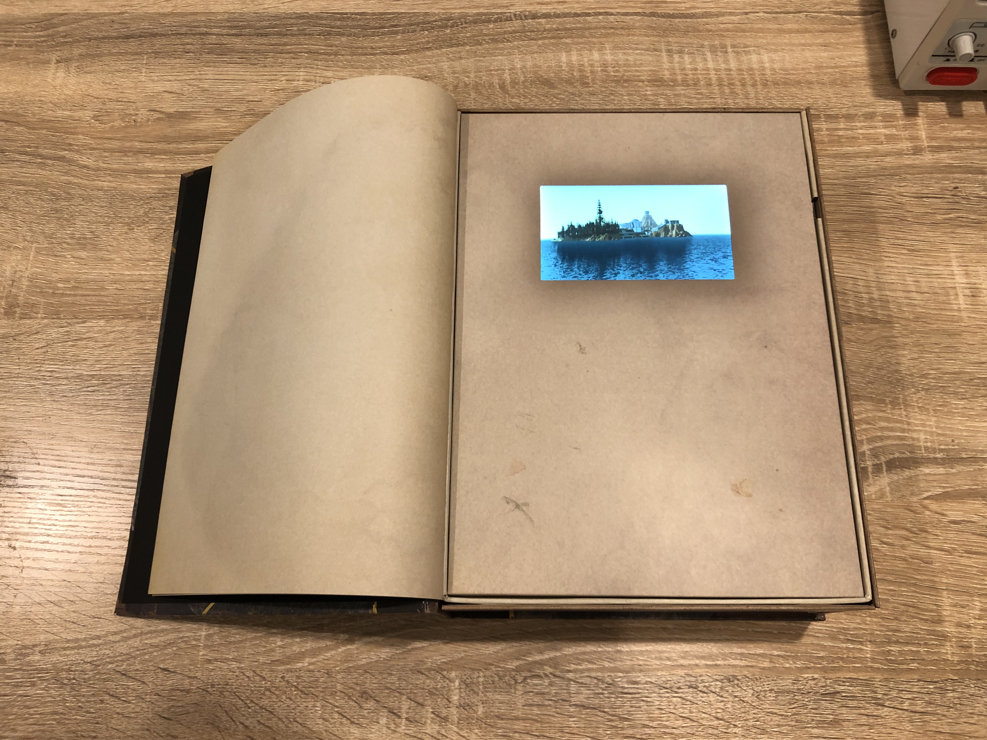
The LCD & Electronics
The book has been enlarged but the linking panel LCD has been kept the same size, so it looks a little smaller than it should be. However it’s sized so that on the lower tier versions the images on the game disc sleeves can be the linking panels themselves, so it’s not like they could’ve made the sleeves much larger. Its colours are bright & vibrant, its got a pretty fantastic viewing angle, and its brightness level has clearly been tuned so it looks “right” for normal indoor brightness levels – as in, it looks close to a window to another world and not a brightly glowing LCD, and it photographs very well. The video plays automatically when you open the book, which is cool, and the battery level indicator displays momentarily in the top right, which is nice I guess but I wish there was some way to turn it off. In case you’re wondering, it’s got a standard 3.7V 800mAh 2.96Wh Lithium battery inside which charges from the included USB cable at 1A. The best way to store this battery long-term is to leave it at around 50% capacity, which isn’t too hard to do given the book has a battery level indicator. Loading alternate videos onto the book seems like it would be easy but I haven’t tried it to see what formats or codecs it can handle. I like the “hidden” button markers that are smudges on the page, they’re sneaky. The speaker in the top right is a bit quiet, a bit tinny and seems to be peaking a lot – I haven’t pulled apart the electronics yet but I think it’s because it’s hidden behind the front paper. There’s only so much you can do when a speaker is obscured like that. I suspect a few holes in the paper would improve the audio quality but pulling that apart is another job.
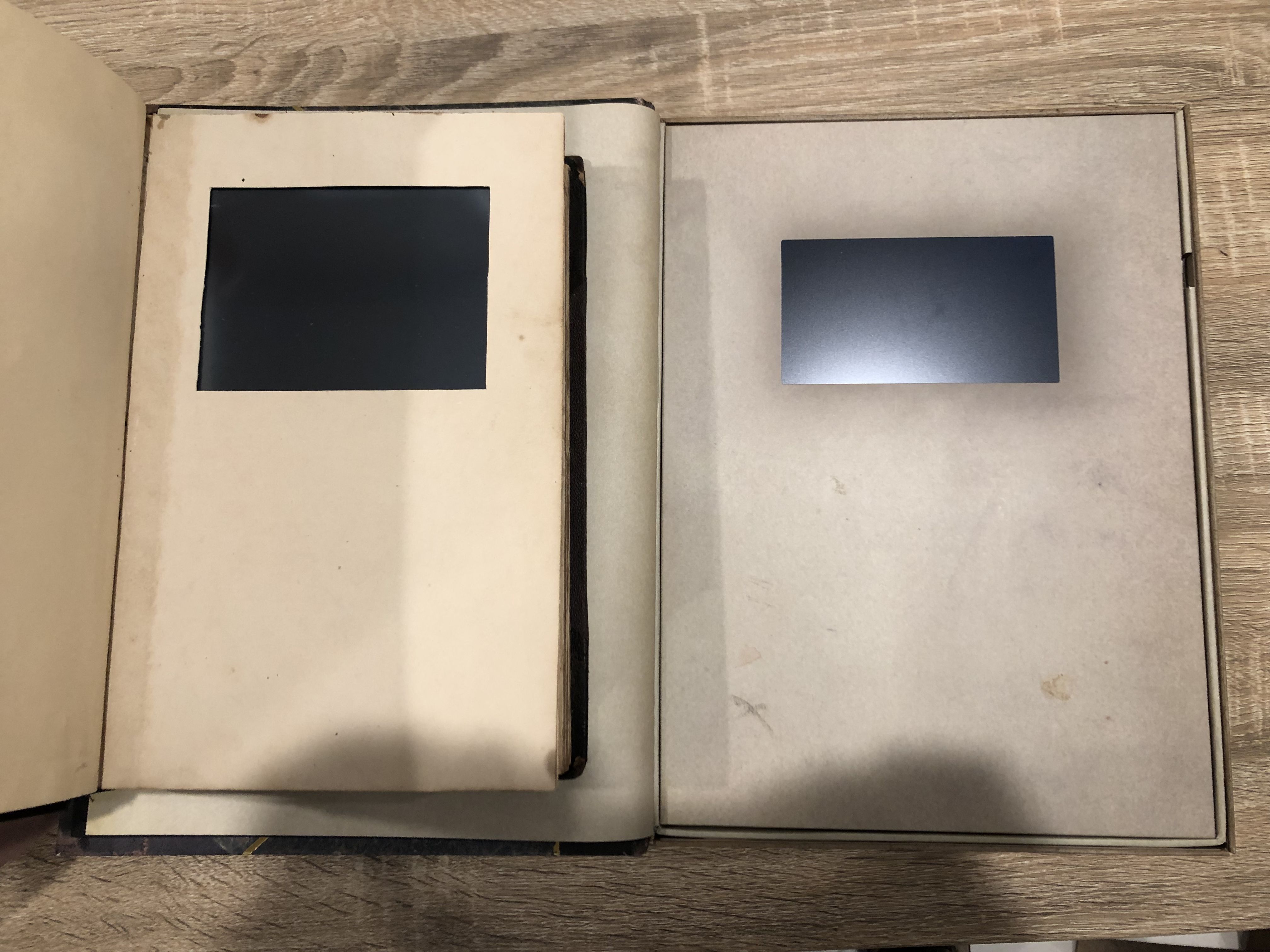
Size comparison of LCDs between my replica and the Kickstarter version – almost the same size LCD except for the aspect ratio
From personal experience I can say that there aren’t many options for suitable LCDs around the right size with the right specs for a linking panel. Particularly if you want 15,000 of them, and you’re not willing to spend $80/panel. For reference the LCD for my Myst book cost $140USD, and that’s for just the raw LCD panel itself without the driver board, embedded computer to feed it content, battery, charging circuitry, etc. Cyan only charged an extra $70 for the tier with all the electronics, so to pull that off at scale their choices would’ve been limited and I’m super impressed they managed to do it on such a comparatively tight budget.
Now, the content on the book. First off – the original classic Myst intro has been re-rendered at 30fps at the resolution of the book, so it looks amazing! 😀 The other content on the book is a bit of a mixed bag and honestly feels a little like they got half-way through making videos for it when they hit the deadline and abruptly stopped. There’s no videos from Revelation or End of Ages, and only a single video from Uru. You totally need to check out the Uru video, UruFly.mp4 – I don’t want to say any more, just play that one and enjoy! Cyanlogo.mp4 looks like a re-rendered version of Cyan’s original 1993 logo just for this book – the blurred text at the end is different but the model is the 3d model is the original one, and it’s crisp like it’s been rendered at the right resolution. There’s plenty of classic Myst, realMyst Masterpiece and even re-rendered classic Myst flyby videos, Sirrus/Achenar/Atrus videos, Riven flybys, and even Exile flybys (even if they are weirdly labelled “Energy” “Jnanin” “Life” and “Matter”)… But no Revelation or End of Ages. It’d be cool if Cyan offers a few flybys from the missing games for download in the future, but who knows if that will happen.
The “extra storage” section contains a bunch of high-res images in here which make me completely drool – I don’t know which have been re-rendered and which are from their archives, but a 4000×1000 pixel panorama of Gehn’s Age is beautiful, Gehn’s Stained Glass is something I don’t remember seeing before, and the 3692×3075 Channelwood photos are so clear I wish I could be there in person.
I hope I don’t get in trouble for sharing this, but it’s located in the book’s readme file, you can find it yourself by literally just searching myst.com for “myst” and 10,000 people are about to know this URL when their books arrive sooo I figure it’s gonna be public soon anyway – you can download a copy of all this from https://myst.com/mystbookfiles/. Get on it and enjoy those high-res images & exclusive re-rendered videos!
I don’t know the full capabilities of the video player but as a data point for you, the main video is an mp4 file with the video in H264 AVC encoded at Level 3.1 complexity, 800×480 resolution, 30fps, ~2367kbps, while the audio’s AAC, 44.1KHz, mono, ~125kbps.
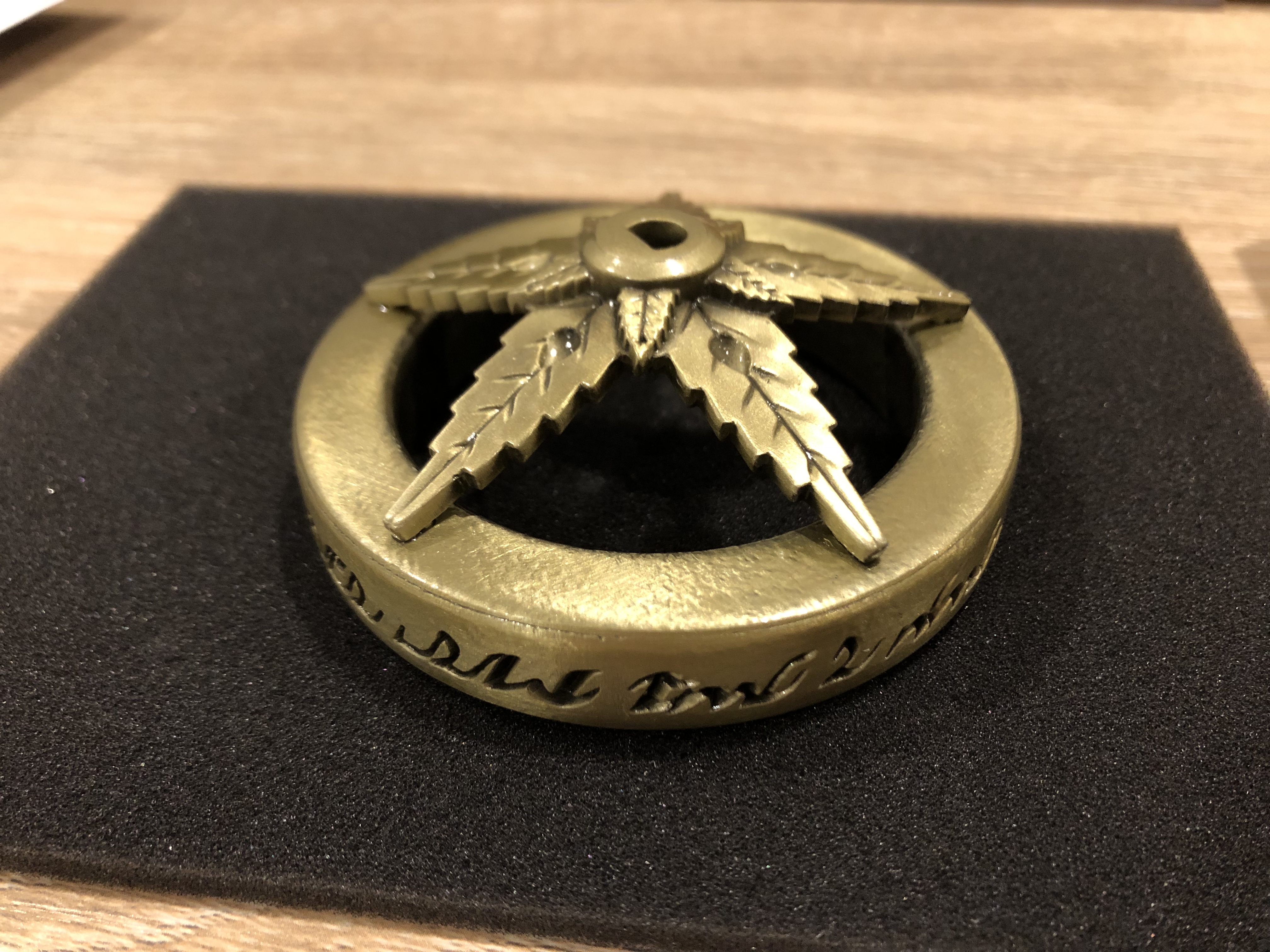
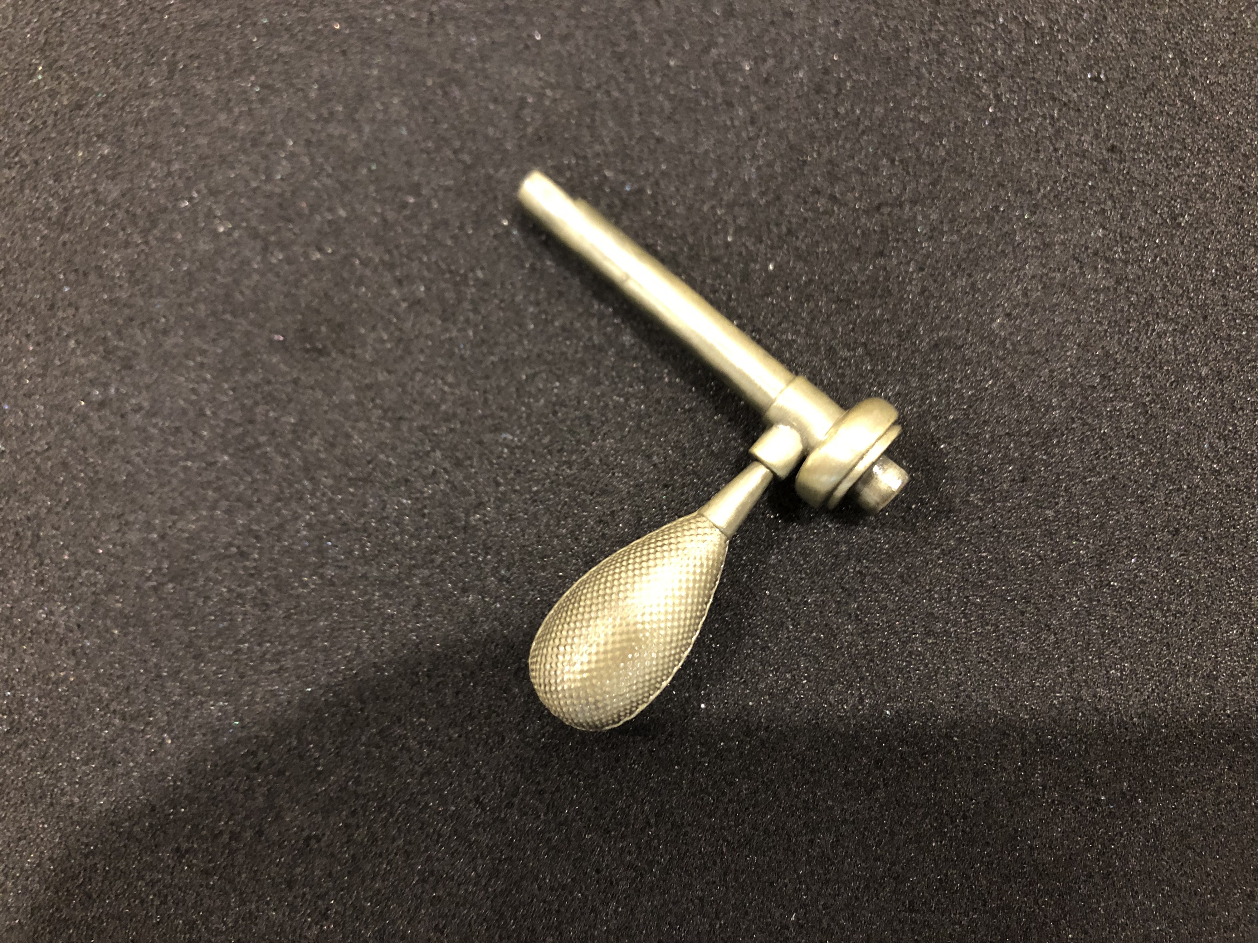
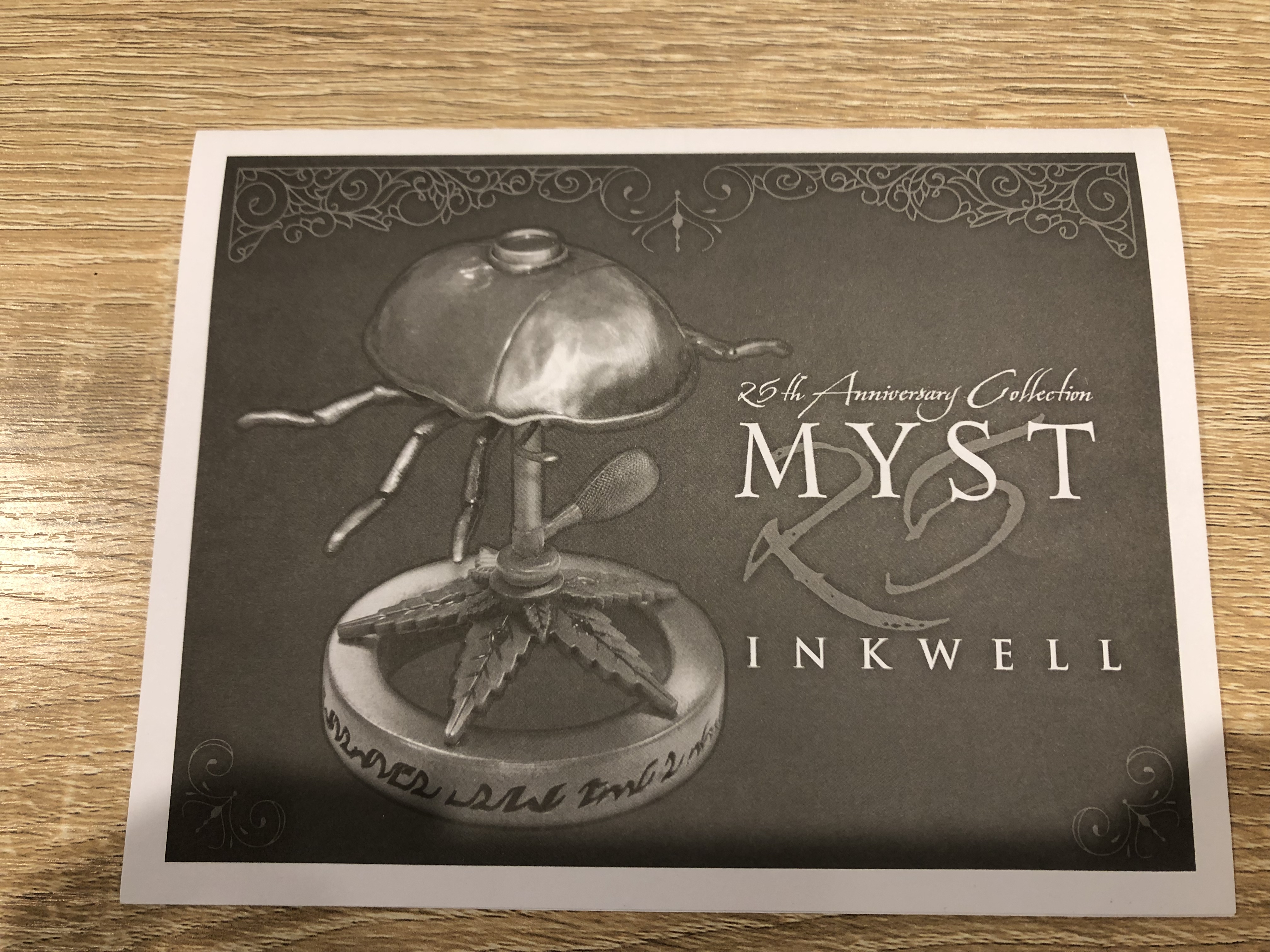
The Inkwell & Pen
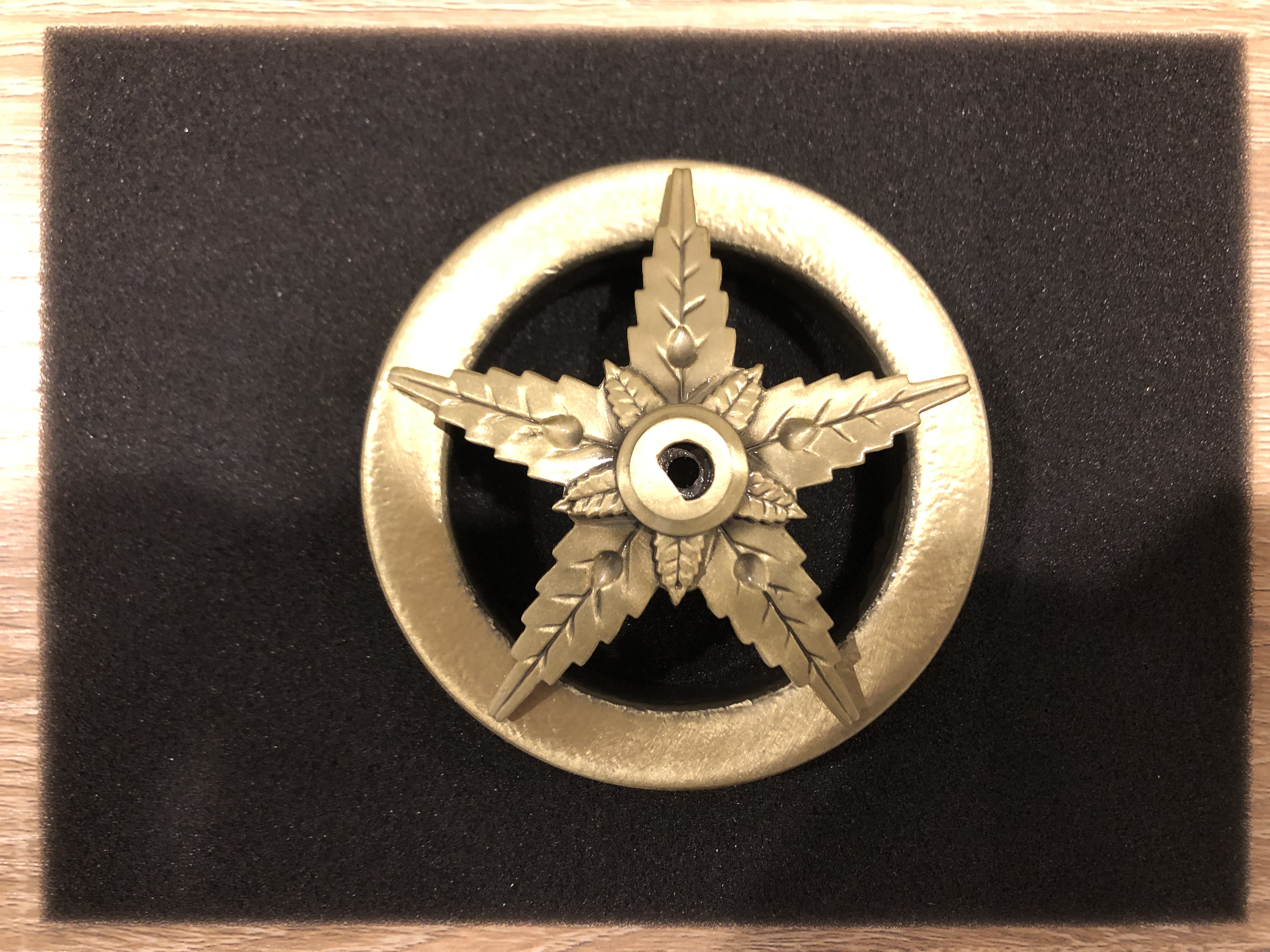
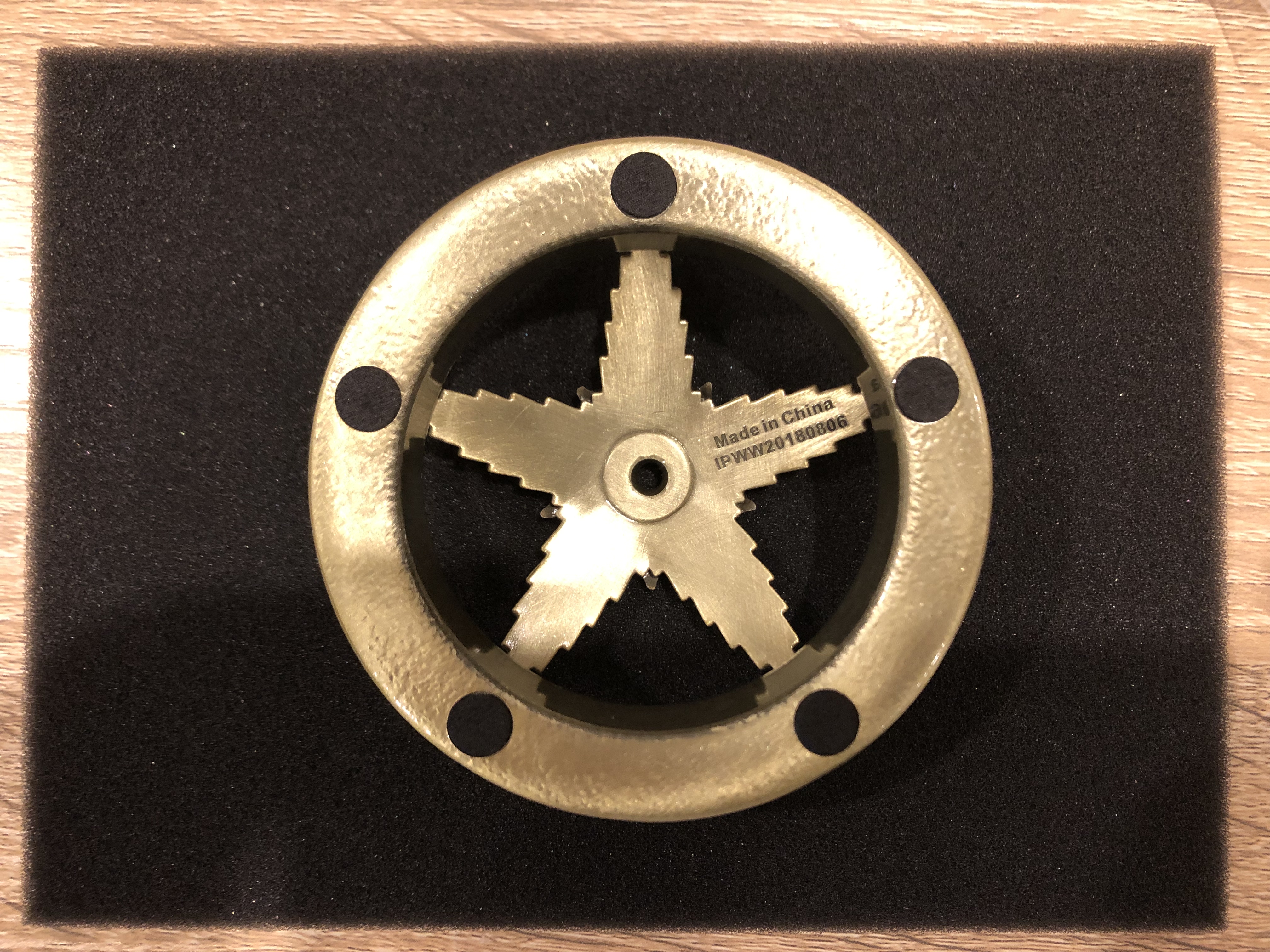
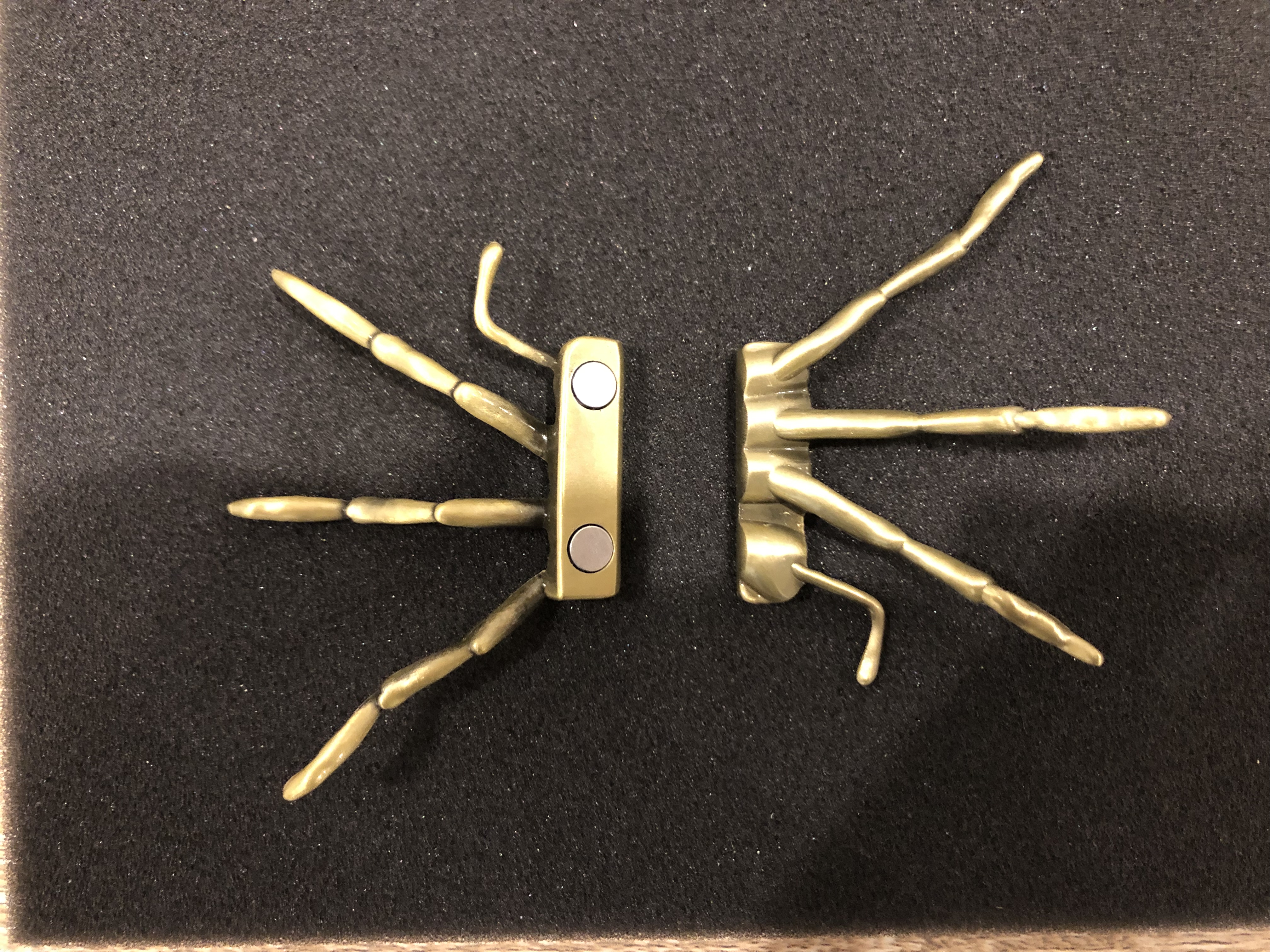
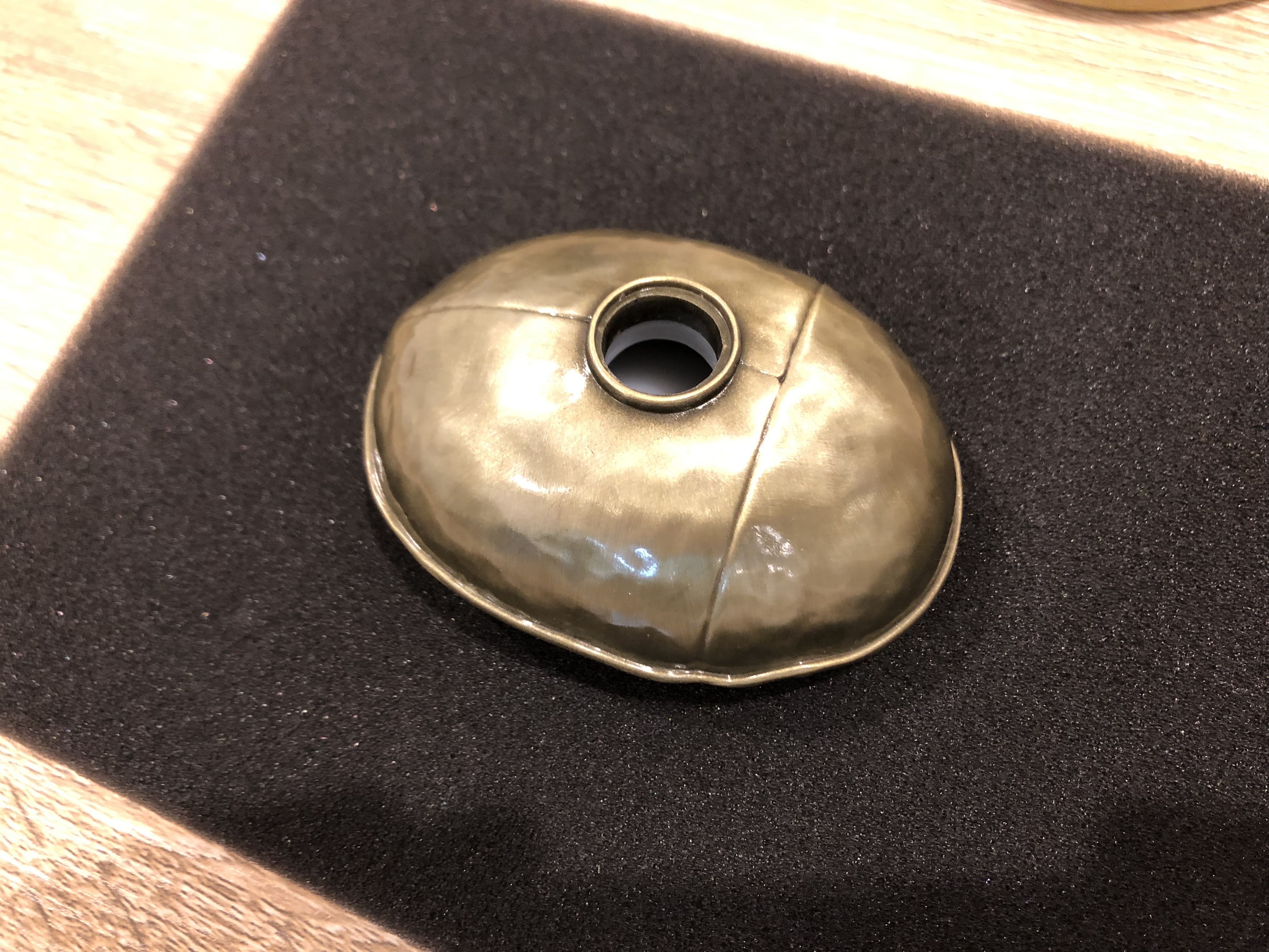
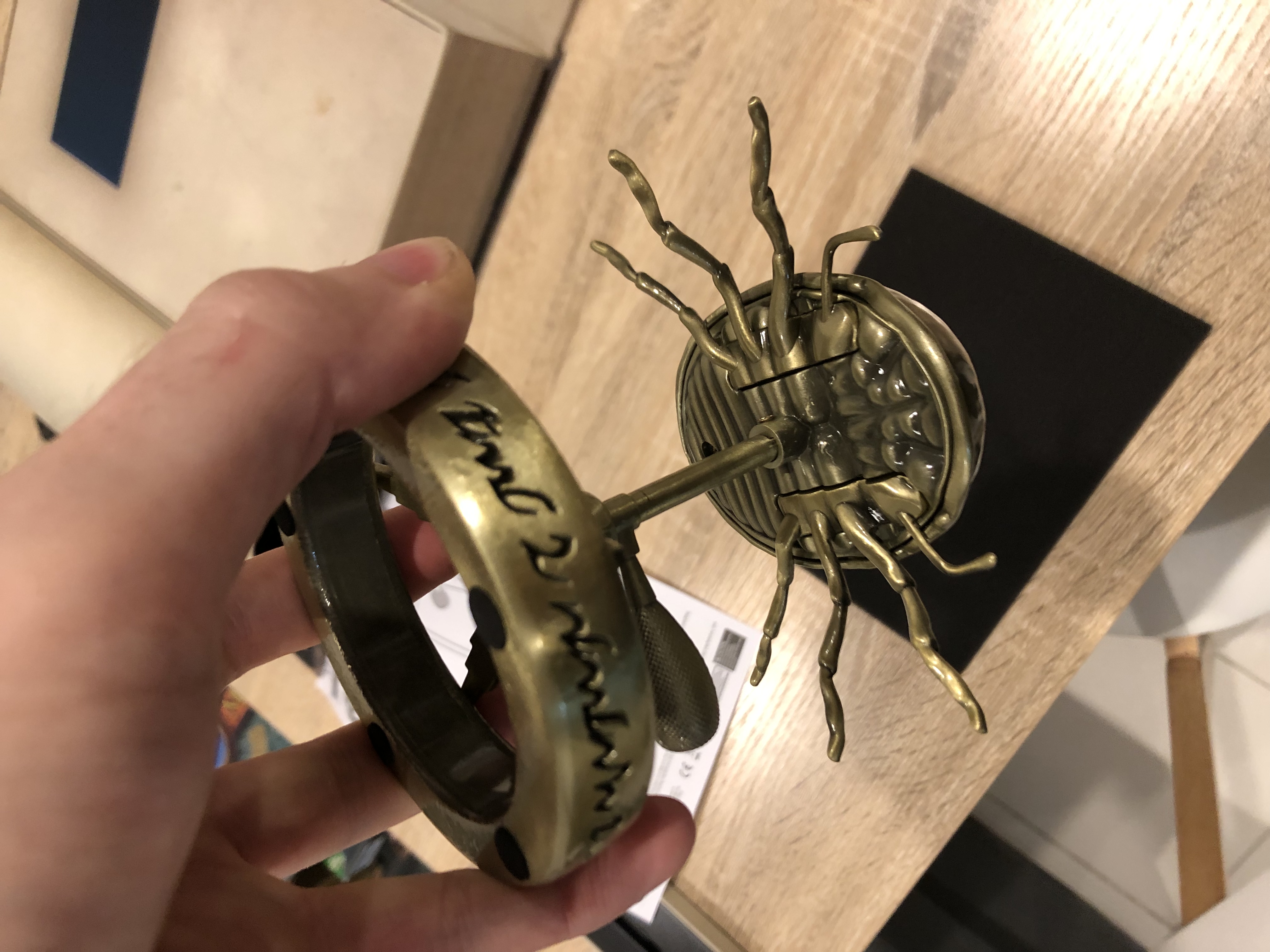
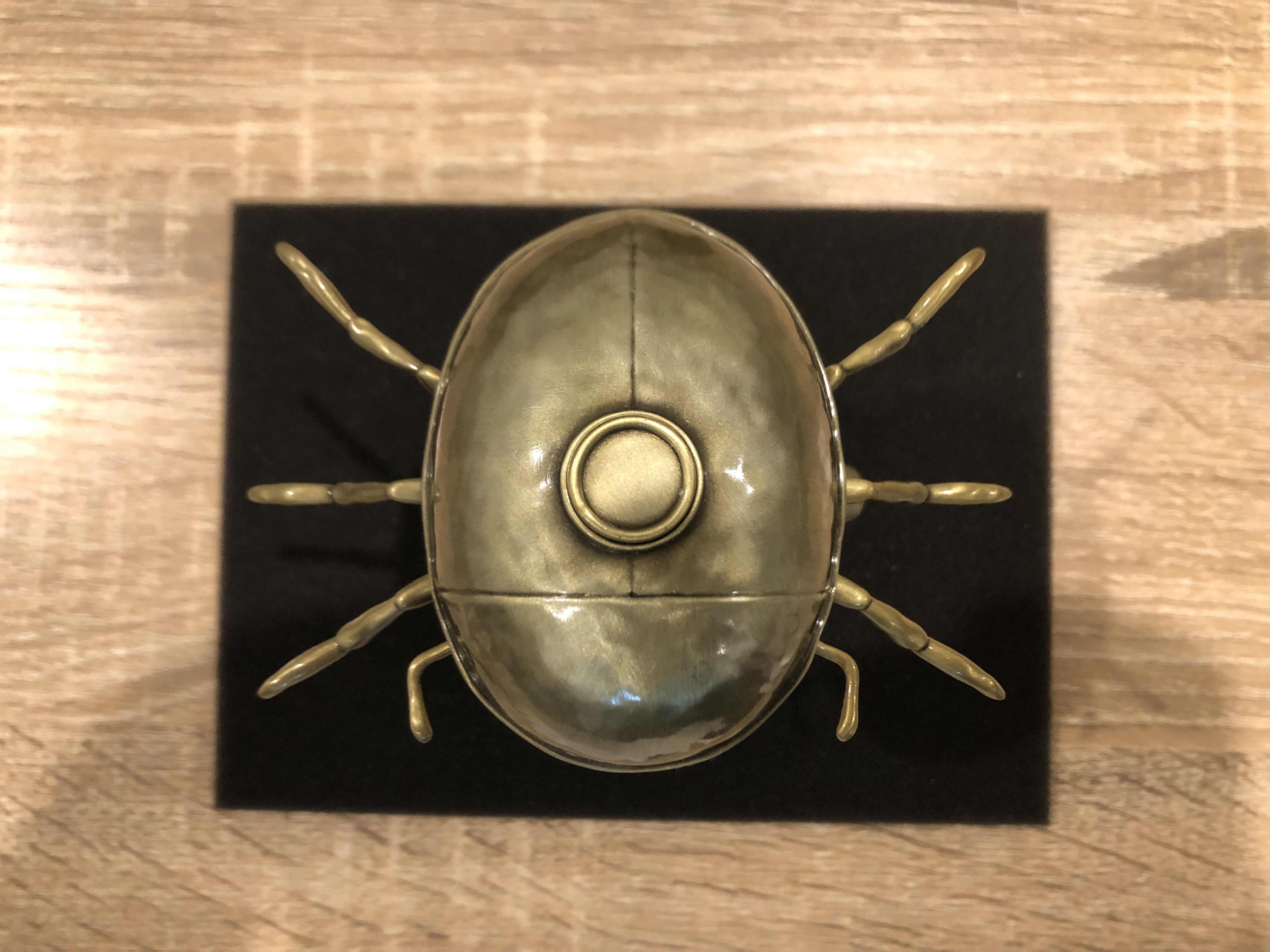
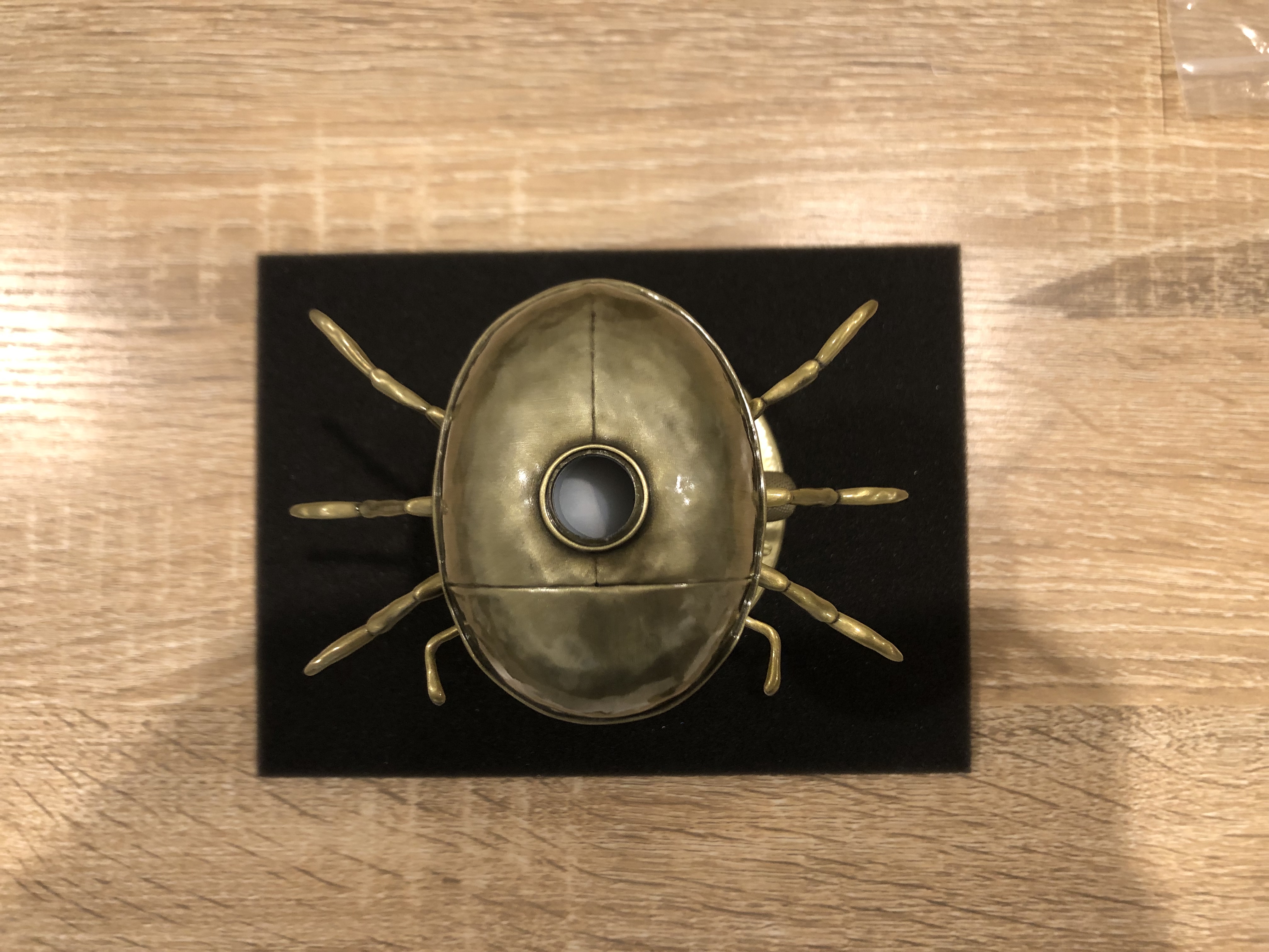
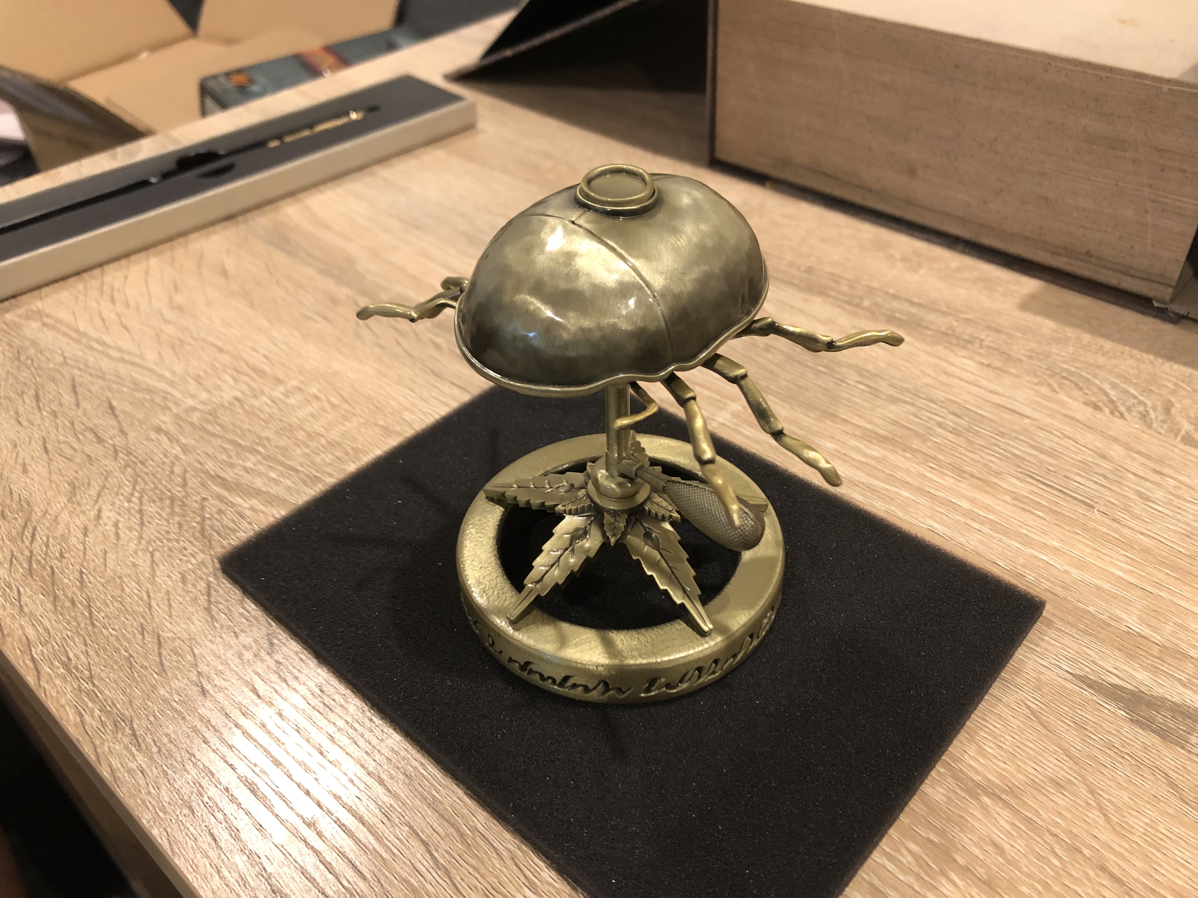
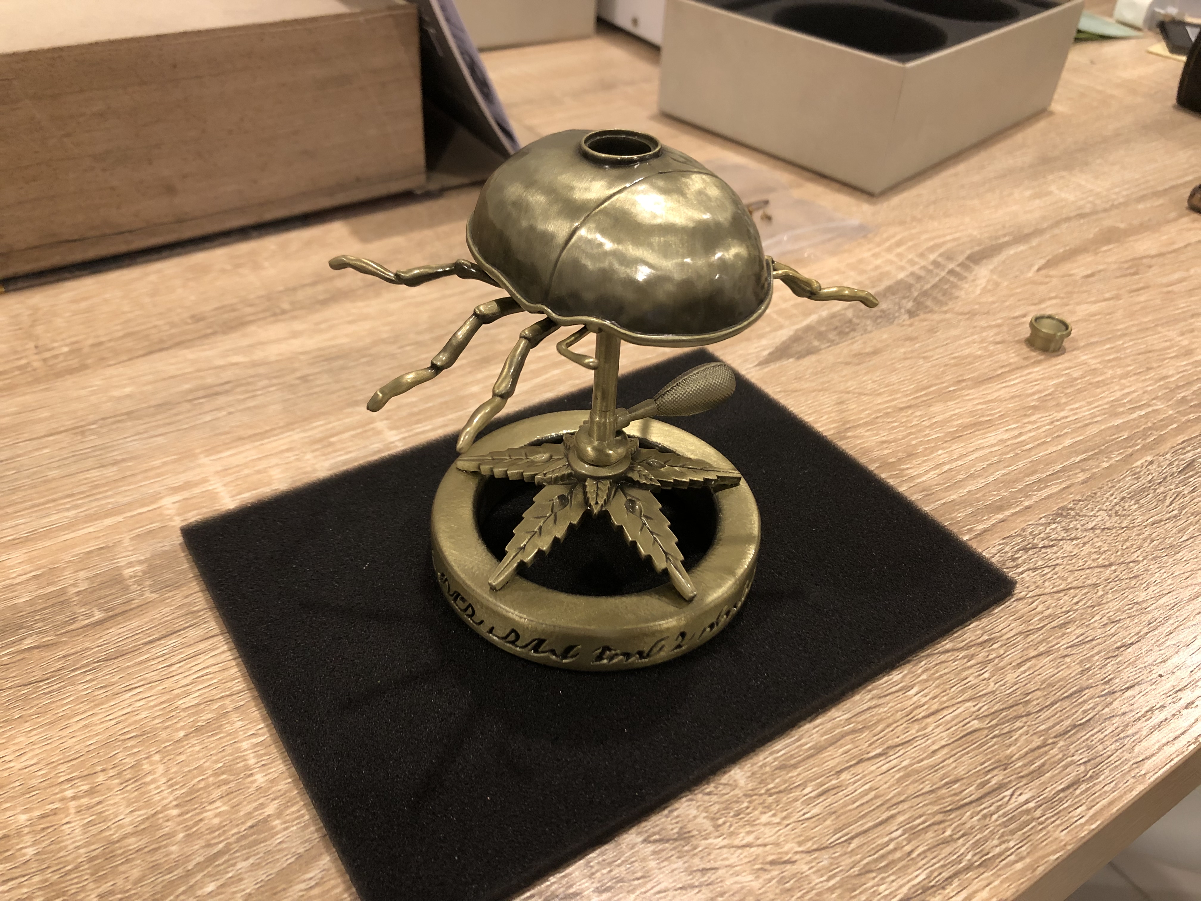
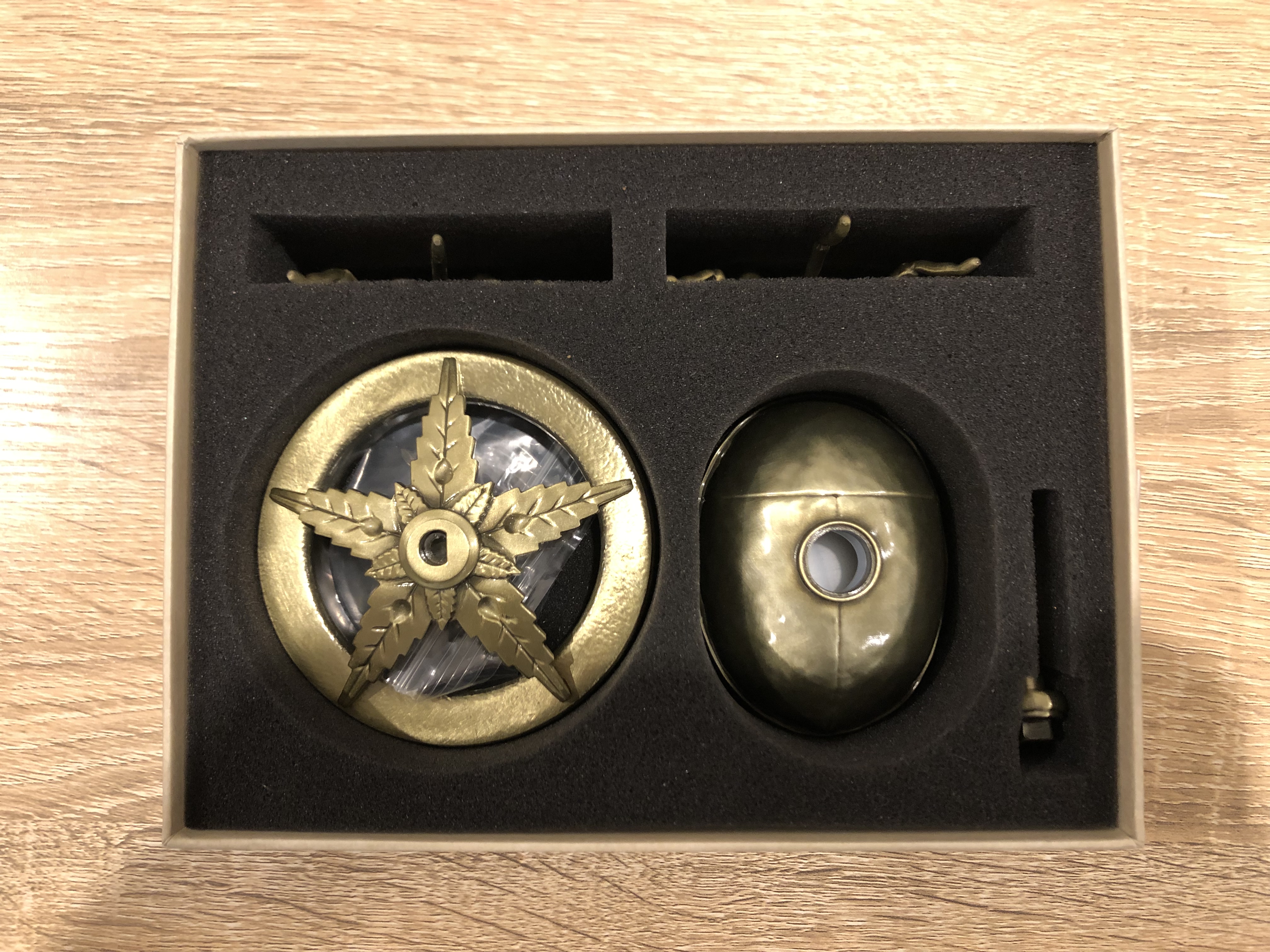
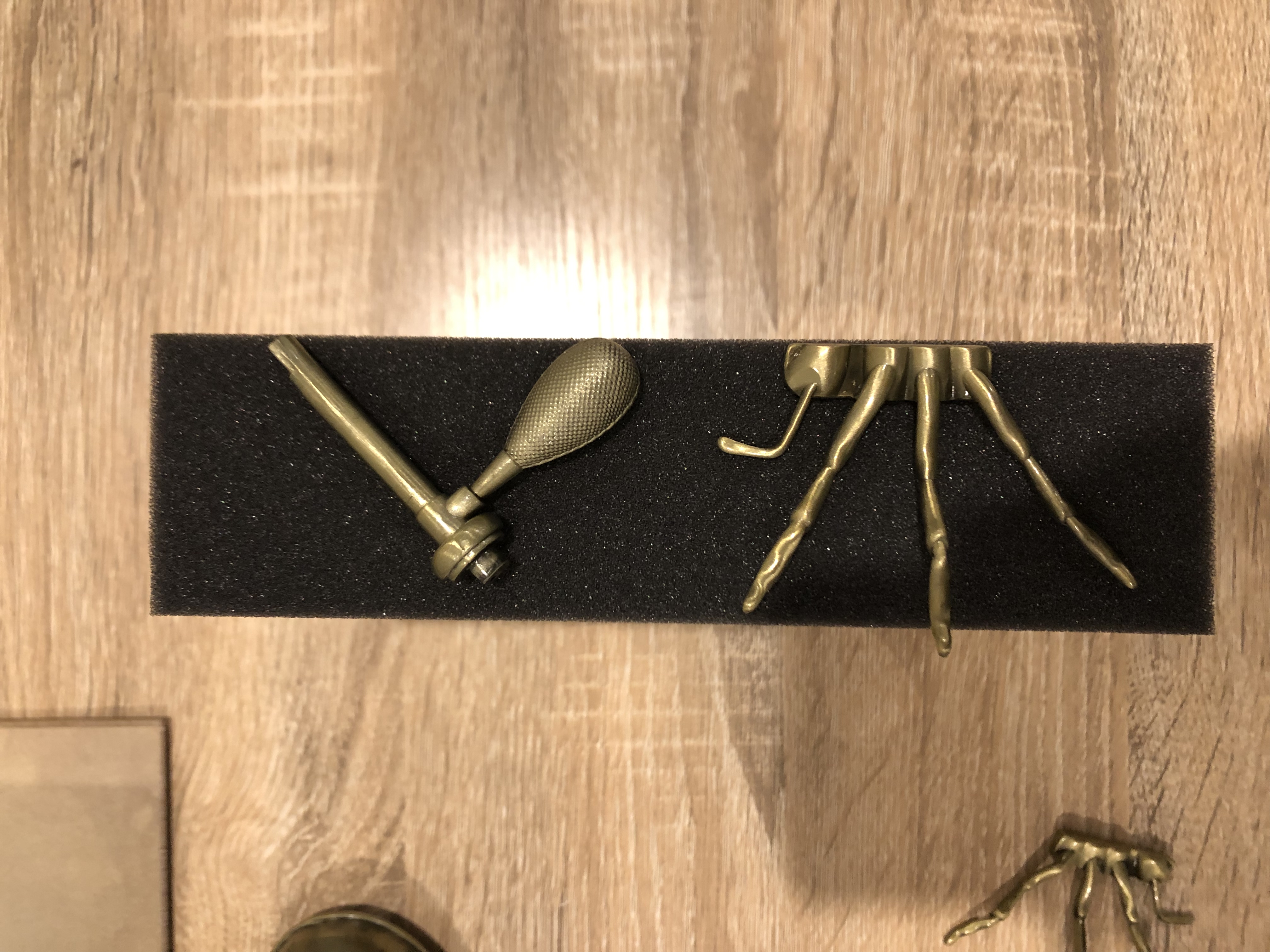
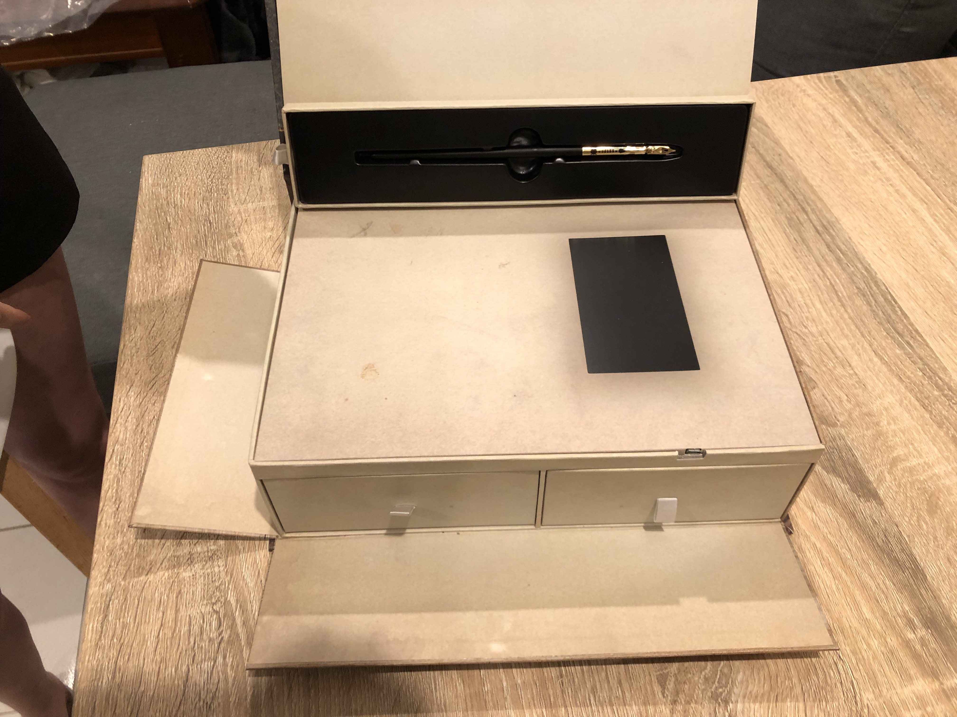
Oh man. This thing is gorgeous. My expectations have been completely blown away. It’s made of what feels like clear-coated brass, and there’s over a dozen separately-cast parts to this thing that have been assembled together into sub-pieces ready for your final assembly via the included screwdriver & two screws (I had four screws; I guess extra in case you lose some). It feels solid & heavy, it feels well machined, and above all it feels well made. The D’ni writing is cast into the actual mould instead of just engraving it. The legs are held on magnetically (which makes the legs handy to use to simulate closing the book while it’s open – the reed switch is in the middle center right). The top has a small plastic bottle hidden inside it to hold the ink (which you can access & completely remove via a screw on the beetle’s underside). And there’s even little rubber feet on the bottom of it – five of them, in fact – which wasn’t necessary but goes to show that every part of this had thought put into it, not just as a quick throwaway thing.
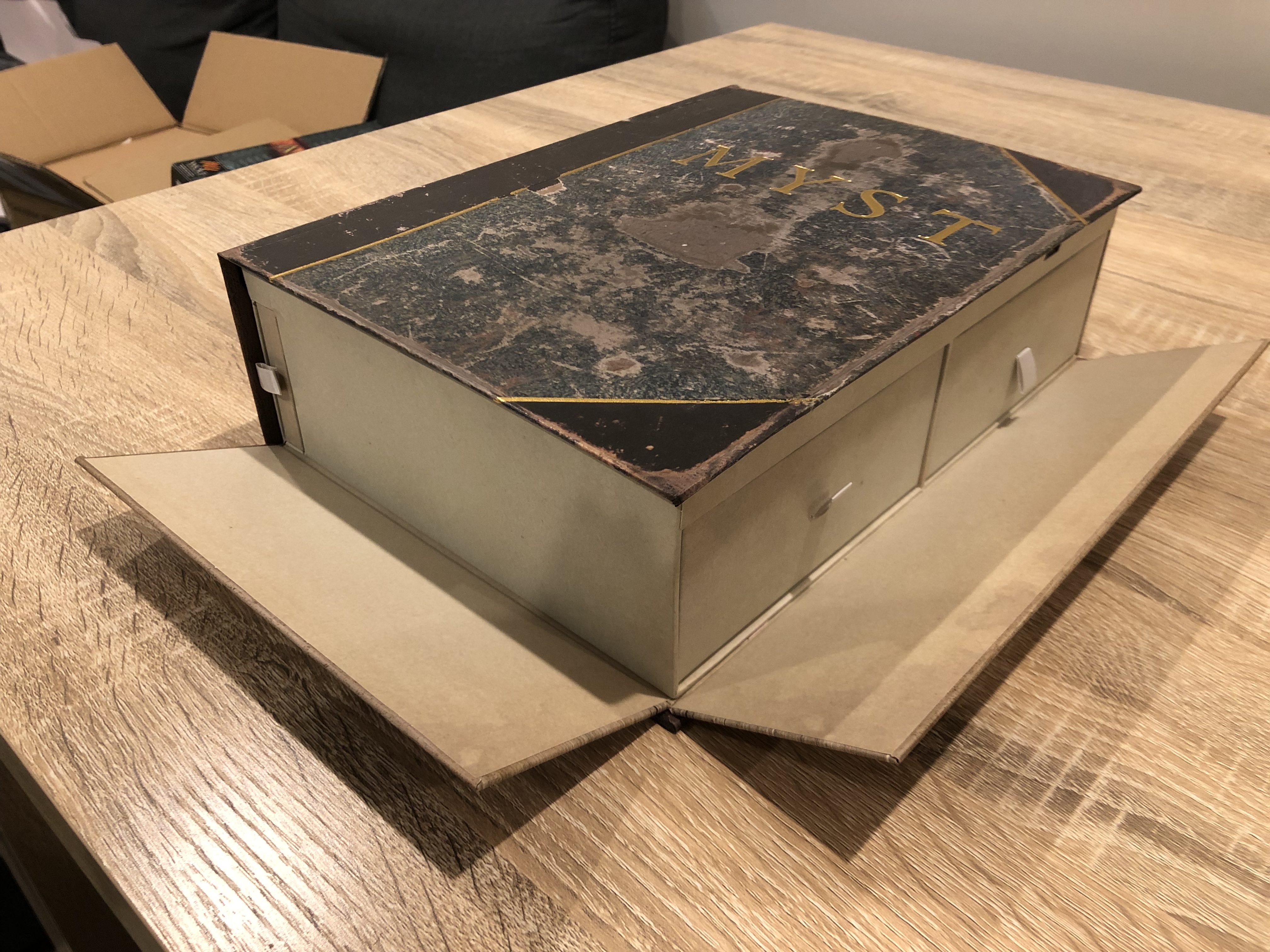
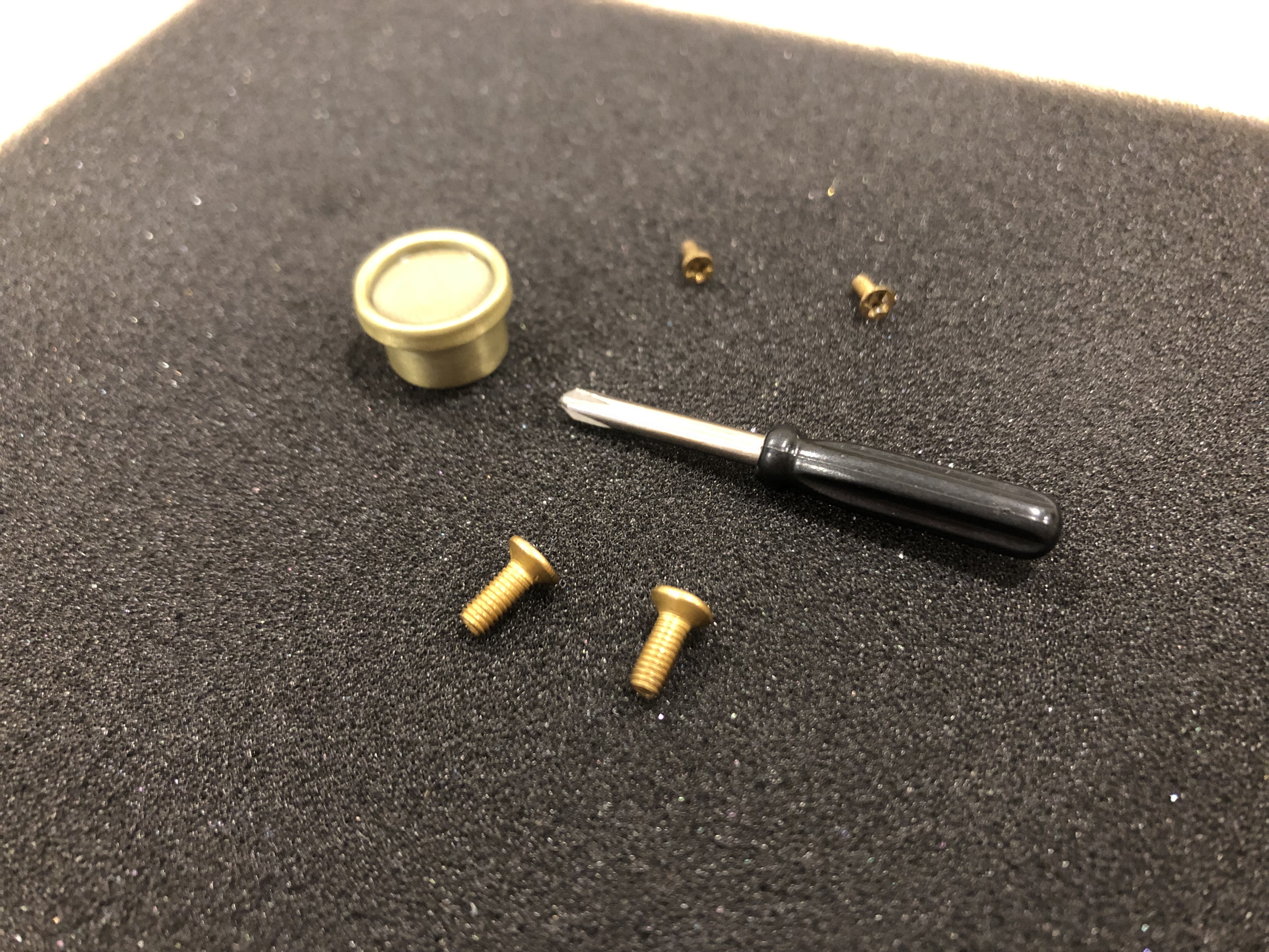
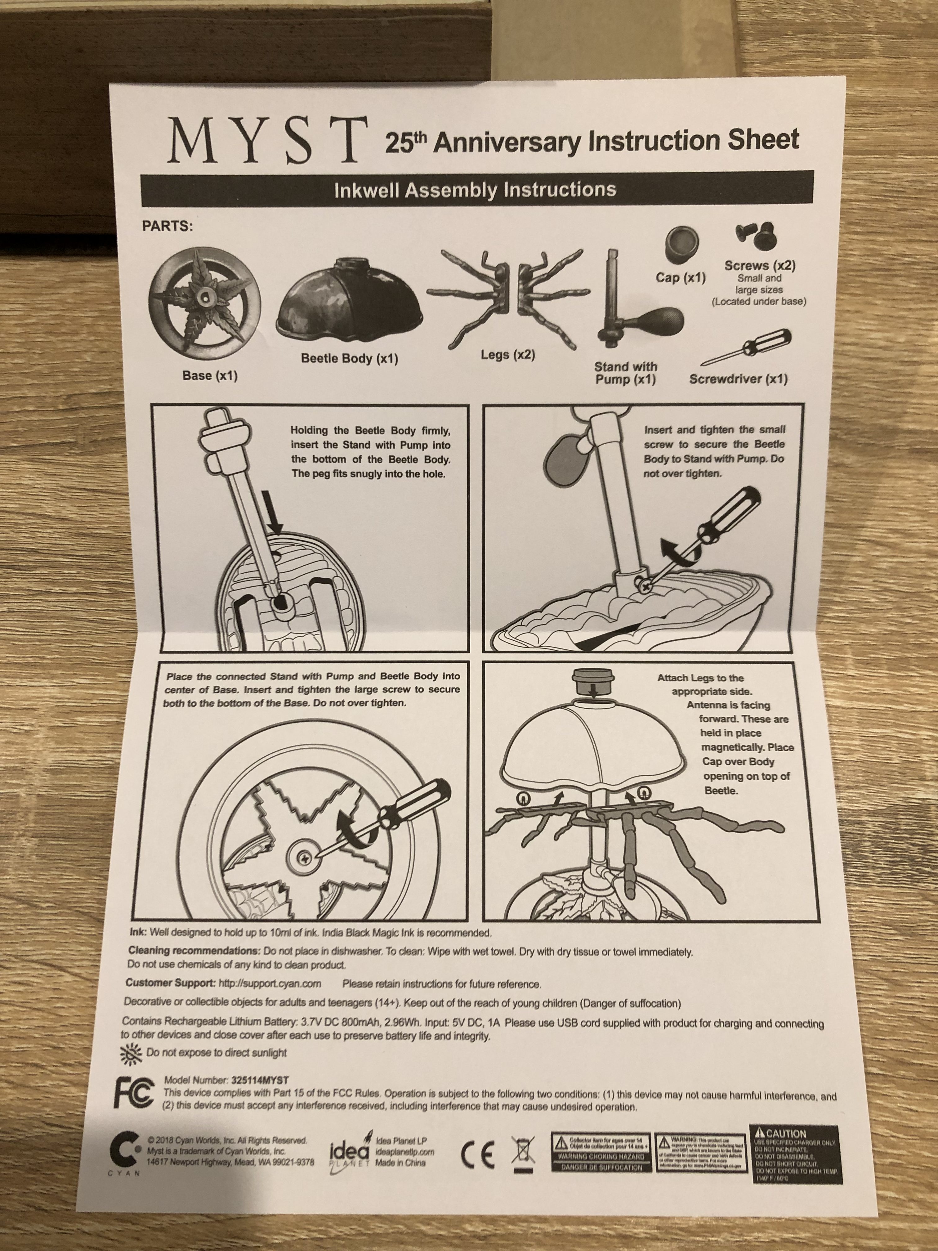
Assembly is pretty easy – the parts are all keyed so they can only go together one way. There’s only two screws involved, both different sizes, and that’s it. But just in case you can’t work it out there’s some instructions included too (the oil smudge on the front page didn’t come with it, whoops). The whole thing comes in a form-fitting foam box to keep everything in place & protected during shipping.
Speaking of the foam box, I’m pretty sure the inkwell is the reason why the book had to be enlarged. Here’s a side-on view of how some of the inkwell pieces fit inside the box. There’s not much width left over. I’m sure some clever 3-dimensional stacking arrangement would’ve been possible, particularly if you’re re-using some of the empty space from the other box, but that would’ve made it all so much more complex than it already is.
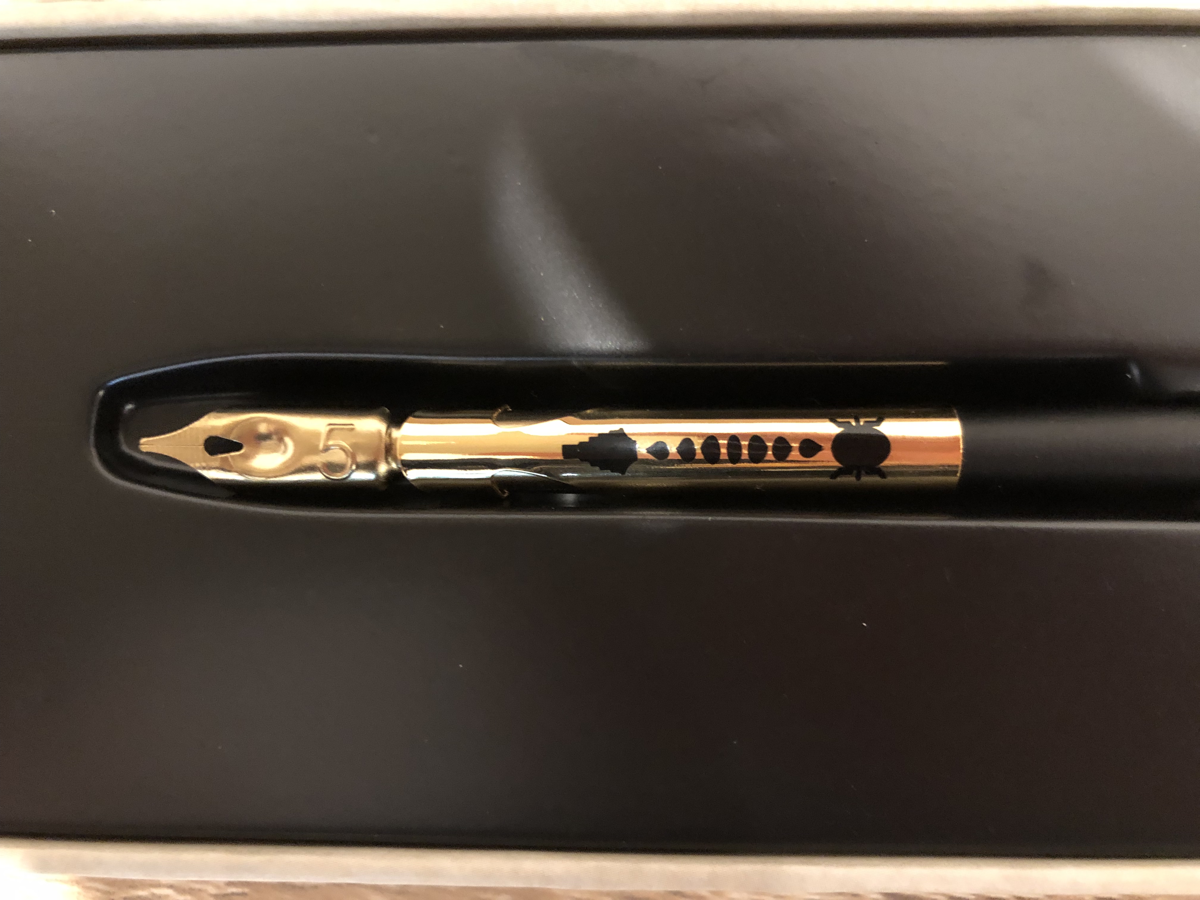
Finally, the dip pen. This looks like a standard pen with a beetle/ink nib marking on the sheath. It’s subtle, but shows that this is a custom part too and not just something they grabbed off the shelf to use unmodified. The included replaceable nib is a #5, because of course it’s that number. If you’re having trouble finding the pen, look below the flap on the bottom edge of the book.
Overall, I gotta say that I’m pretty happy with these rewards. It definitely feels like I got my money’s worth, and the end results are higher quality than anticipated. I’m one satisfied backer!
If you haven’t already heard, Cyan are running a Kickstarter campaign for Myst’s 25th anniversary! For $99USD you can get a copy of all the games (including the elusive 3 & 4), updated for modern Windows & Mac computers, plus it comes in a box that looks like a Myst linking book. Or for $169USD you can get a book that has a small LCD screen as the linking panel that plays videos, just like a real linking book. Fancy!
It’s no surprise where part of the idea for a Myst book with a screen inside it likely came from. To quote Rand Miller (Cyan’s CEO and Atrus actor) from the Kickstarter Live AMA, “we’re doing a book with a real linking panel because we’ve wanted one ever since RIUM+ did his”. There’s nothing much I can add to that quote, really. 😛 I plan to do a full teardown & comparison of Cyan’s one once mine arrives (UPDATE: teardown & comparison blog post here!. For what it’s worth though, based what specs I’ve seen so far their implementation carries my personal tick of approval – it looks like it will do a fantastic job and make a beautiful product for a reasonable price.
But that’s not what this post is about. This one’s about music. It’s been over a decade since I last played the piano so I’m a little bit rusty, but I’ve dusted off the old skills for a very special purpose.
In honour of the Myst 25th Anniversary Kickstarter, I decided to transcribe & play a piano rendition of Cyan’s logo music!
It just so happens that 10 Instrumental covers is one of the #Myst25 Community Goals. And I have word straight from one of the people managing the Kickstarter’s community goals that the Cyan intro theme music counts. As such, here’s the files so you can play it too!
A couple notes on these (pun intended) – both the chord complexity and their representations are sitting in the middle between being perfect representations and being easy to play. By this I mean that I’m skipping a few notes from the chords as I wanted it to be reasonably easily playable on an actual piano, and the timing in the sheet music isn’t 100% spot-on because doing that was far more complicated to describe & decipher than I thought was worth it. Feel free to adapt this to a different instrument, add or remove notes for your own personal style, or fiddle with the timing in the midi file if you’re only intending digital playback.
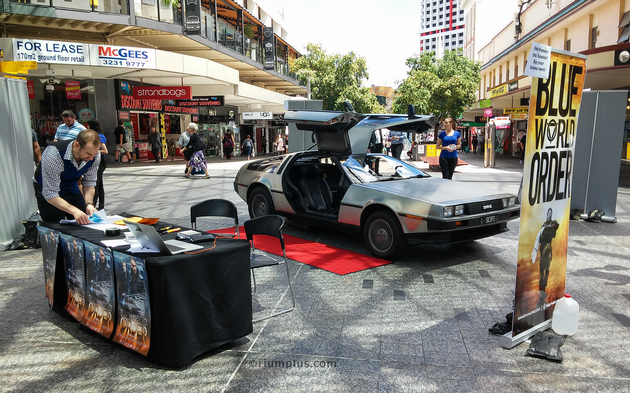
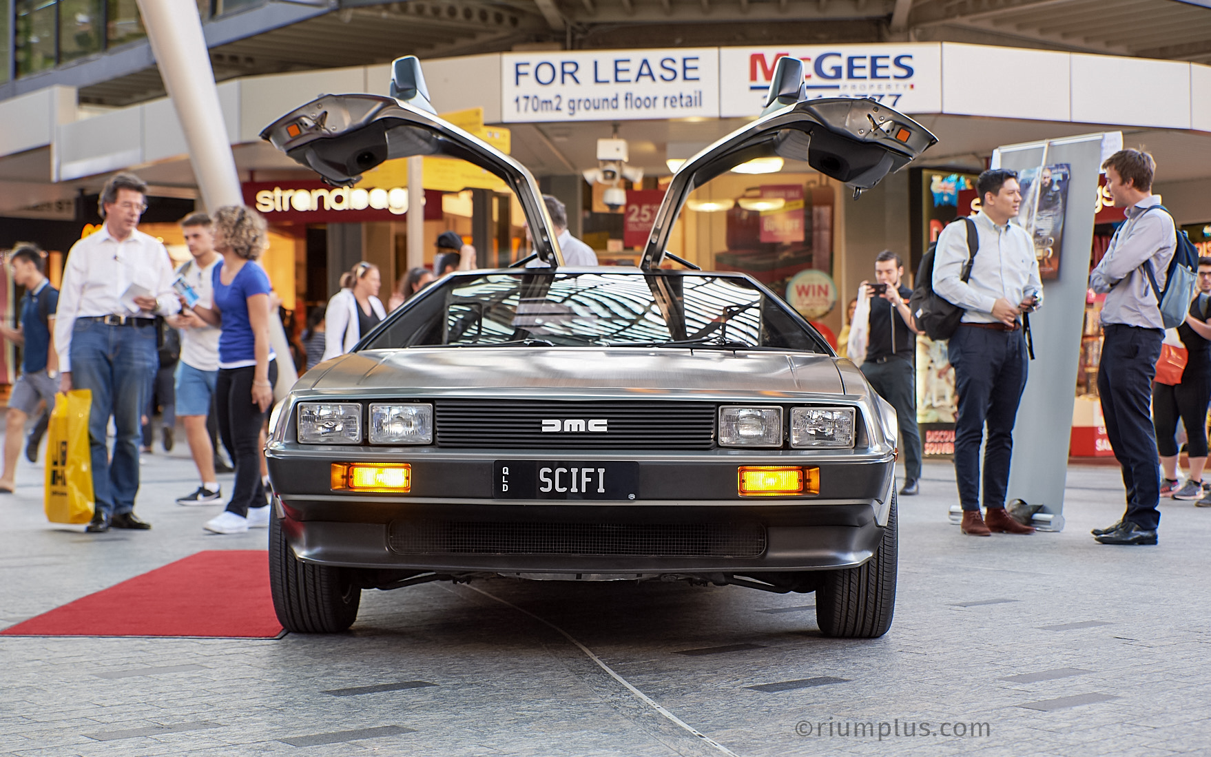
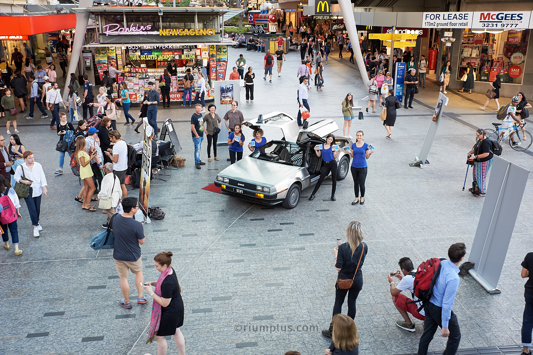
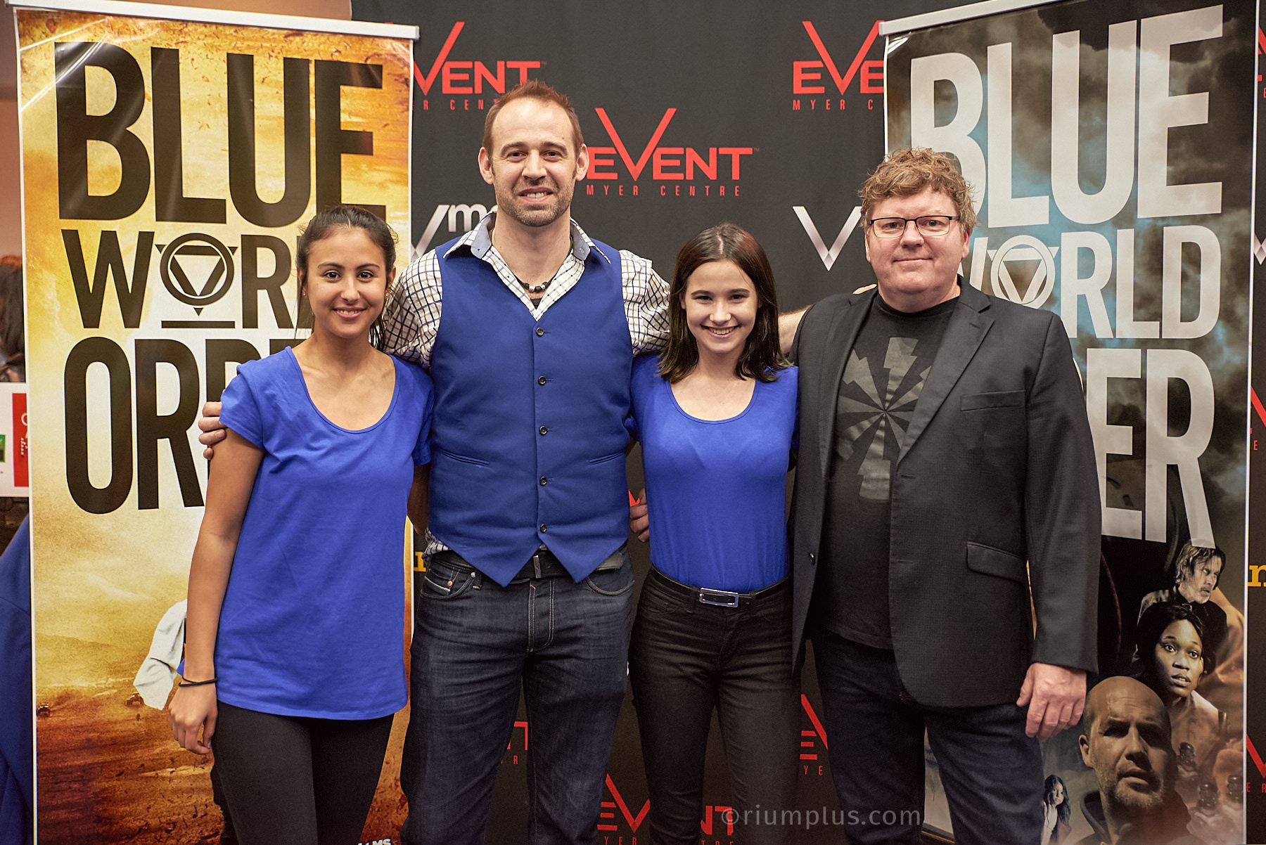
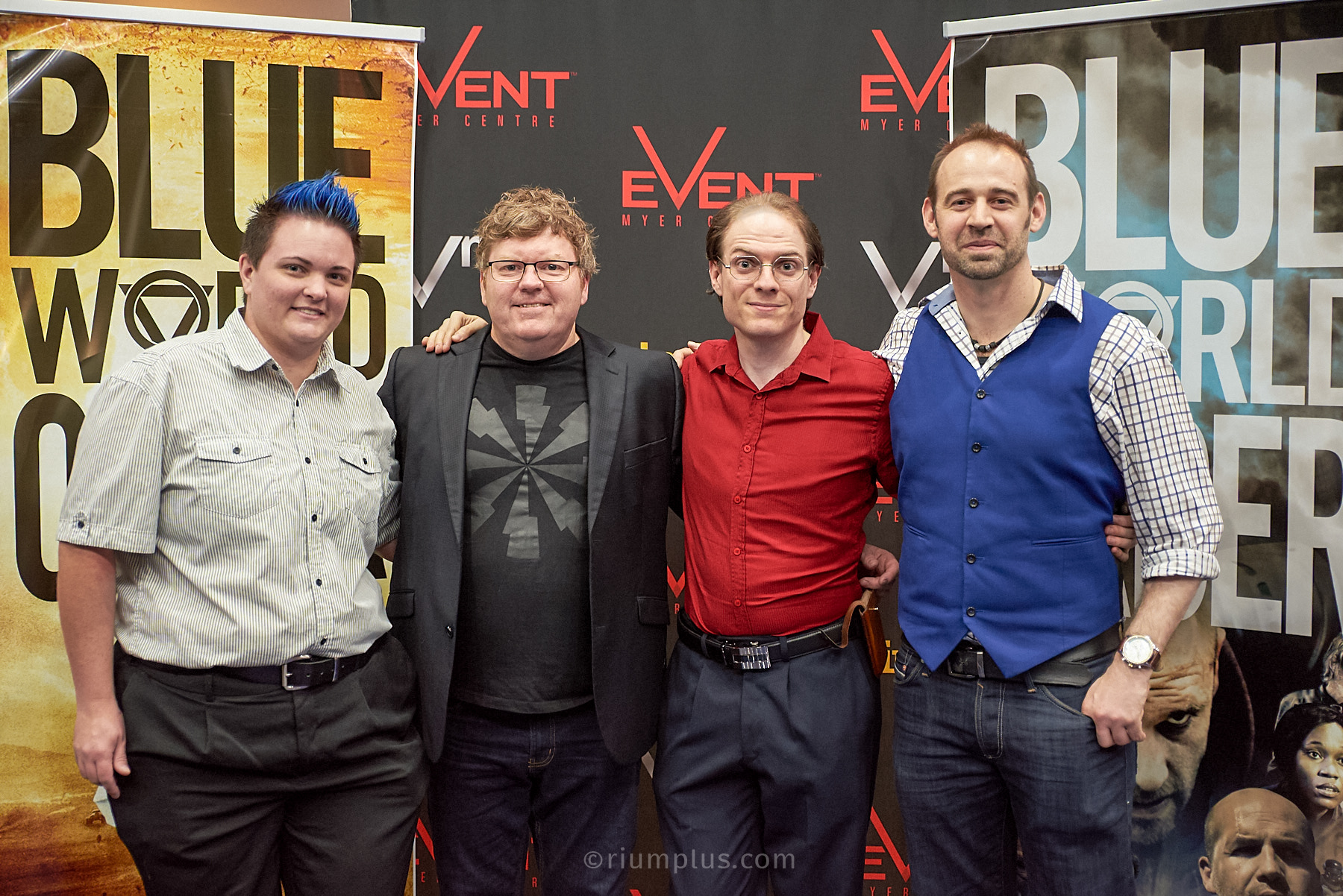
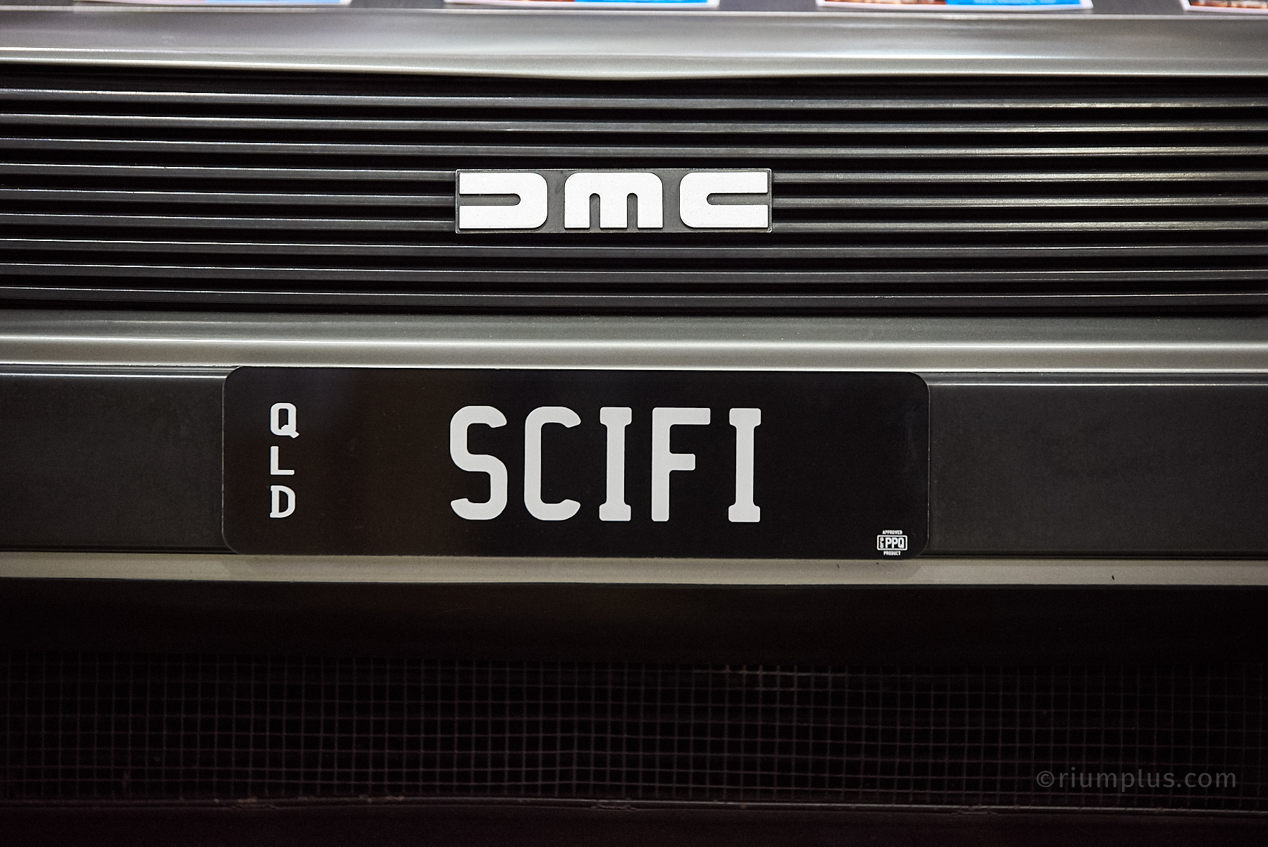
In late 2017 my DeLorean was used for promoting the indie Aussie film Blue World Order. Produced by Matthew Reilly and directed by Ché Baker, it’s a post-apocalyptic science fiction film set in the Australian wasteland. One of the scenes involves a car chase with a whole fleet of DeLoreans – mine specifically wasn’t used in filming, but given they all look very similar there was no reason to bother shipping one up here to Brisbane when mine’s already here. So my car was used for the 2017 Gold Coast Supanova, 2017 Brisbane Supanova and for promoting the QLD premiere of the movie in Queen Street Mall.
My DeLorean at a pop culture convention like Supanova isn’t anything too unusual, but my DeLorean sitting in the middle of Queen St Mall is something else. That area is one of (if not the) busiest pedestrian areas in the state with a constant flow of people the whole day long.
Check the Blue World Order website for where you can watch the full movie! But for now, here’s some photos from the various events. My DeLorean is available for hire/rent in Brisbane, the Gold Coast, Ipswich, Toowoomba, Redcliffe, Caboolture & surrounding areas for weddings, photoshoots, corporate events/functions, filming, high school formals and joyrides. I’ll even optionally dress up as Doc Brown or Marty McFly if that’s what you want! Contact me today.
I’m Mike Ando, a time-travelling mad scientist. DeLorean driver. Satellite owner. Inventor. Potato connoisseur. Once on Beauty & the Geek Australia, now a Professional Geek.


