It’s been so long since I updated my personal website, I decided to just start from scratch with a whole new one. Something that’s not, well, entirely coded by hand in Notepad so maybe I’ll be more likely to update it as updates will be easier. I’ll re-add more old content whenever I get around to it.
This website isn’t the only thing that’s new though, I’ve just finished another round of modernising the Riven Journals – just in time for Riven’s 20th anniversary!
What’s new:
The background music now plays on more modern browsers (including on most smartphones)
There’s a new compatibility shim to display the mouse hover text, which replaces window.status which has been deprecated for quite some time
All Perl code has been modified to work with newer versions of the language, which means the cookie handling parts work properly again. This means all .cgi pages work, there’s no more script errors, and Journal 5 is actually completeable now
All PHP code has been modified to work with version 7 of the language
Personally checked that the Easter Eggs are actually accessible, since no one’s found them yet (they’re pretty hard to find!)
A couple logic errors have been corrected (which were present in the original Riven Journals… I have no idea how I missed them for so long)
The Prefetching code has been updated with more hints, which should make browsing around the Riven Journals super fast with very quick page load times
Checked to make extra sure the Easter Egg content is accessible
And if that’s not tempting enough for you, in honour of Riven’s 20th anniversary I’m unveiling some exclusive, previously-unreleased, never-before-seen Riven concept art of the schoolroom Wahrk counting number game:
Like in many areas, the DeLorean’s cooling system is a little bit different when compared to the average modern car. The coolant radiator is still in the front, but the engine’s mounted in the rear. This not only makes for a very long coolant loop that takes a lot of fluid, but also means the system has multiple high points – meaning you have to bleed the air bubbles out of multiple places. The system wasn’t really designed with ease of maintenance in mind, but thankfully there’s a few upgrades/modifications you can do to make this job easier! So today I’ll be installing one of DeLorean Parts NorthWest’s Wings-B-Cool modifications, a radiator bleeder kit. This procedure can theoretically be done on the car as-is if you’re small & flexible, but I highly recommend jacking up the front right corner & removing the front right wheel to give you plenty of space to work in.
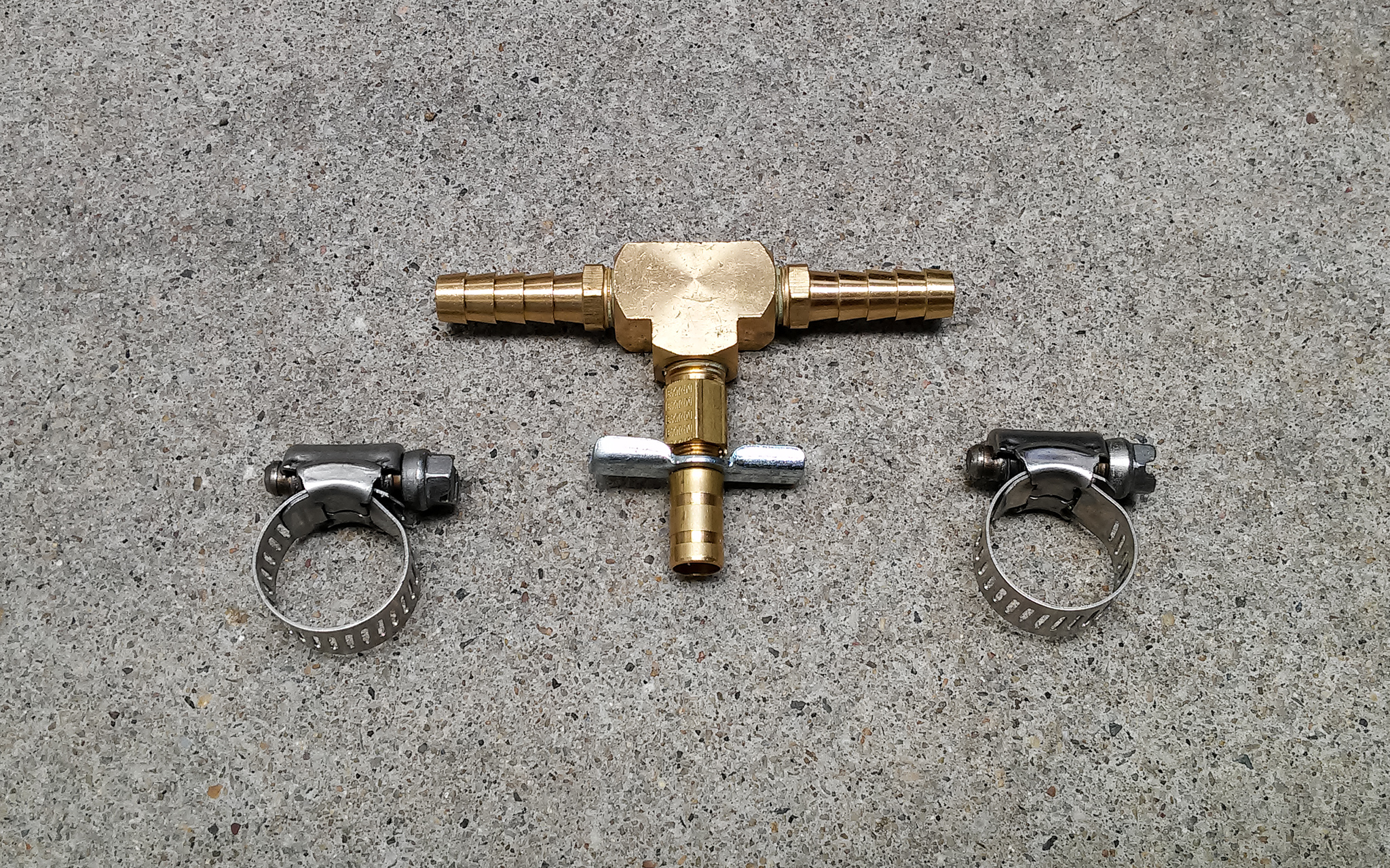
The best hacks are the simplest ones. This mod consists of nothing more than a T-valve, hose clips, and some temporary clear hose only used when bleeding (not pictured)
The normal procedure for bleeding the DeLorean’s radiator involves disconnecting a hose, having boiling hot coolant spray all over you in sputtering bursts between the air bubbles, then reattaching the hose again when you think you’ve got rid of all the bubbles. Even worse, if you have the original radiator, the hose barb is plastic and after 35+ years this plastic is very brittle and likely to crack on you, which means you have to replace the entire radiator. Thankfully I have an upgraded metal radiator, but even still it’s not a pleasant procedure. I did it once and swore that I’d do this modification before I had to change my coolant again.
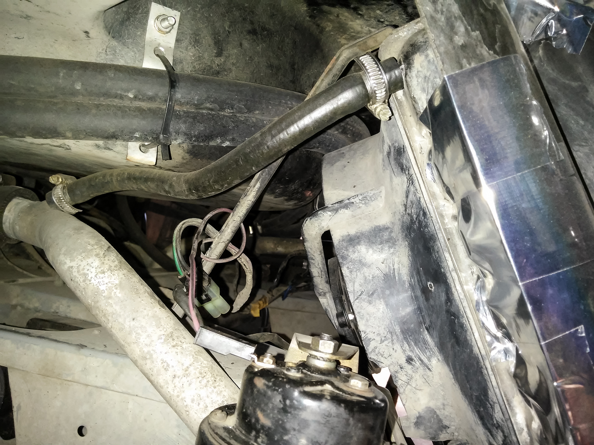
The radiator return connectors – the lower metal pipe is the main coolant return line, while the upper flexible hose is an attempt at a self-bleeding system. It doesn’t really work and you still have to remove this hose to manually bleed the system
The procedure for this mod is pretty simple – clamp off the hose (or drain your coolant system), cut out a segment of the hose, insert & replace that segment with the kit’s T-valve. I have some clamps specifically designed to close off coolant lines which made this job super simple. I recommend either investing in a pair or borrowing/renting them if you’re planning to do this job without draining the coolant system, because otherwise you’ll end up with coolant everywhere.
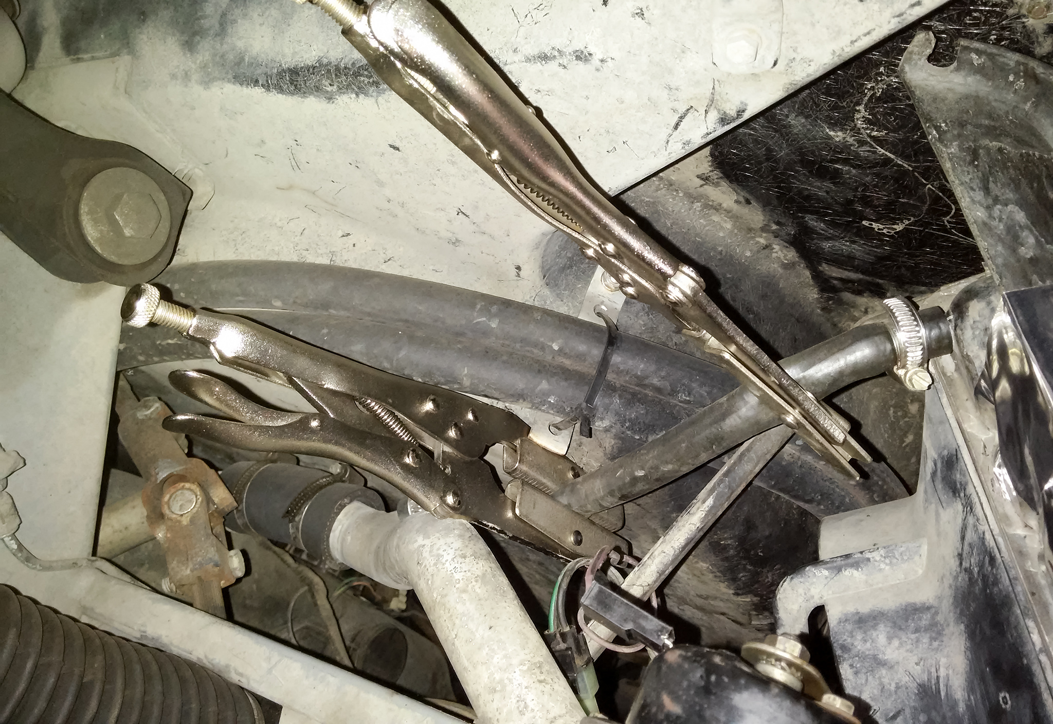
Coolant bleeding hose clamped off & ready to be cut
Cutting a segment of this hose is probably the most difficult part of this job – and that’s not hard to do at all, which says something about how easy this mod is.
To operate the new coolant radiator bleeder, simply attach a temporary hose to the barb on the T-valve that leads into a suitable container, turn on the car, bring the engine up to operating temperature when the cooling fans cycle, then open the valve. When you no longer see air bubbles in the clear tube, turn off the valve & remove the hose and you’re done – it’s that simple! You might want to do this in multiple goes, topping up the coolant reservoir when necessary to make sure it doesn’t run out – if it gets too low you’ll just introduce more air into the system and then you’ll have to bleed the engine too.
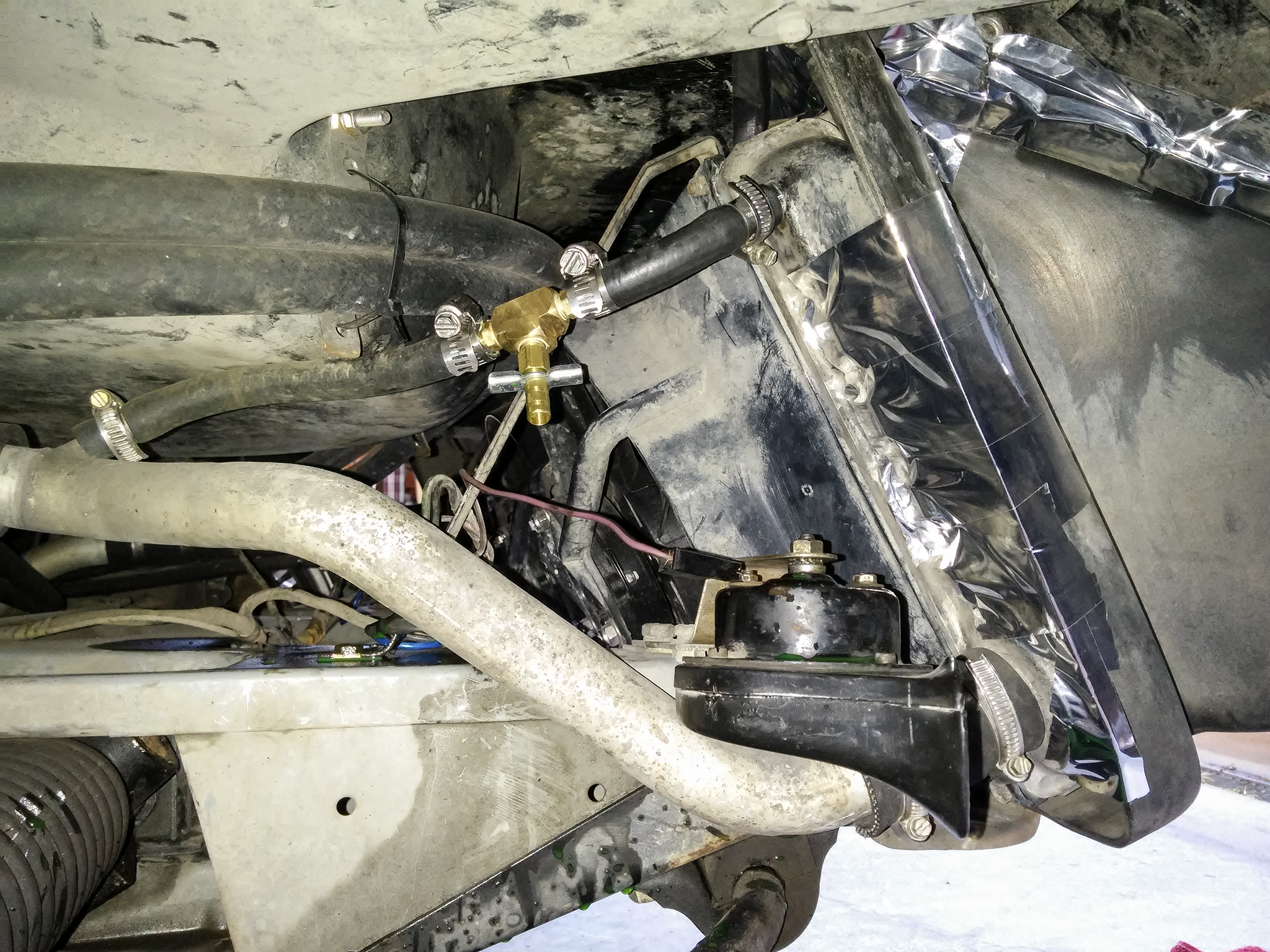
T-valve installed in place with my radiator freshly bled
You can also see another mod I recently did to the car on the right of this image – I taped up the gaps between the radiator & its shroud with metal ducting tape (which is a different product to duct tape that is designed to stay stuck at a wide temperature range and also when wet). This means more air goes through the radiator itself instead of going around it through the gaps. I’ve noticed it’s helped my engine stay a little bit cooler, but not by much – I would only recommend it if you have large gaps around your shroud and you also live in a hot climate, but don’t expect it to work any miracles for you. Properly bleeding the radiator will have a larger impact.
Once this radiator bleeder kit was all installed, I bled my radiator with the T-valve just to check it all worked. Interestingly enough, even though I had already bled my system before, I still got a few more air bubbles out of it this time. I guess that goes to show how much more effective this bleeder is vs removing & reattaching the entire hose! I would totally recommend this upgrade to other DeLorean owners, it’s well worth the small price to eliminate a messy job.
Not all the work I do on my car is fixing things or upgrading parts – sometimes I do regular maintenance too. For instance, flushing & changing my brake fluid – it’d been a few years since I last did this job and it needs to be done regularly, particularly on older cars that don’t have sealed brake systems. Plus, I also had some air bubbles in my brake lines that I needed to remove. Aside from the fact that all automotive fluids slowly degrade with time, brake fluid in particular is usually very hygroscopic (meaning it absorbs water very easily, even pulling moisture from humidity out of the air). Most brake fluid has additives that let it tolerate a certain amount of water, but it’s not very much. If it exceeds this limit, it’ll start rusting things in your brake system from the inside – which is even more concerning when you consider that brake fluid itself is highly corrosive if it touches the wrong things.
It’s also important to make sure you change the fluid in the brake lines themselves, not just the fluid in the main reservoir. Brake systems need to be bled of any air bubbles, too – if there’s air bubbles your brake pedal will feel spongy and won’t work as well as it should. There’s a procedure to follow for this that varies between cars, and the DeLorean uses a different order than the usual due to the car’s unique configuration, so be sure to find out the correct process before you start.
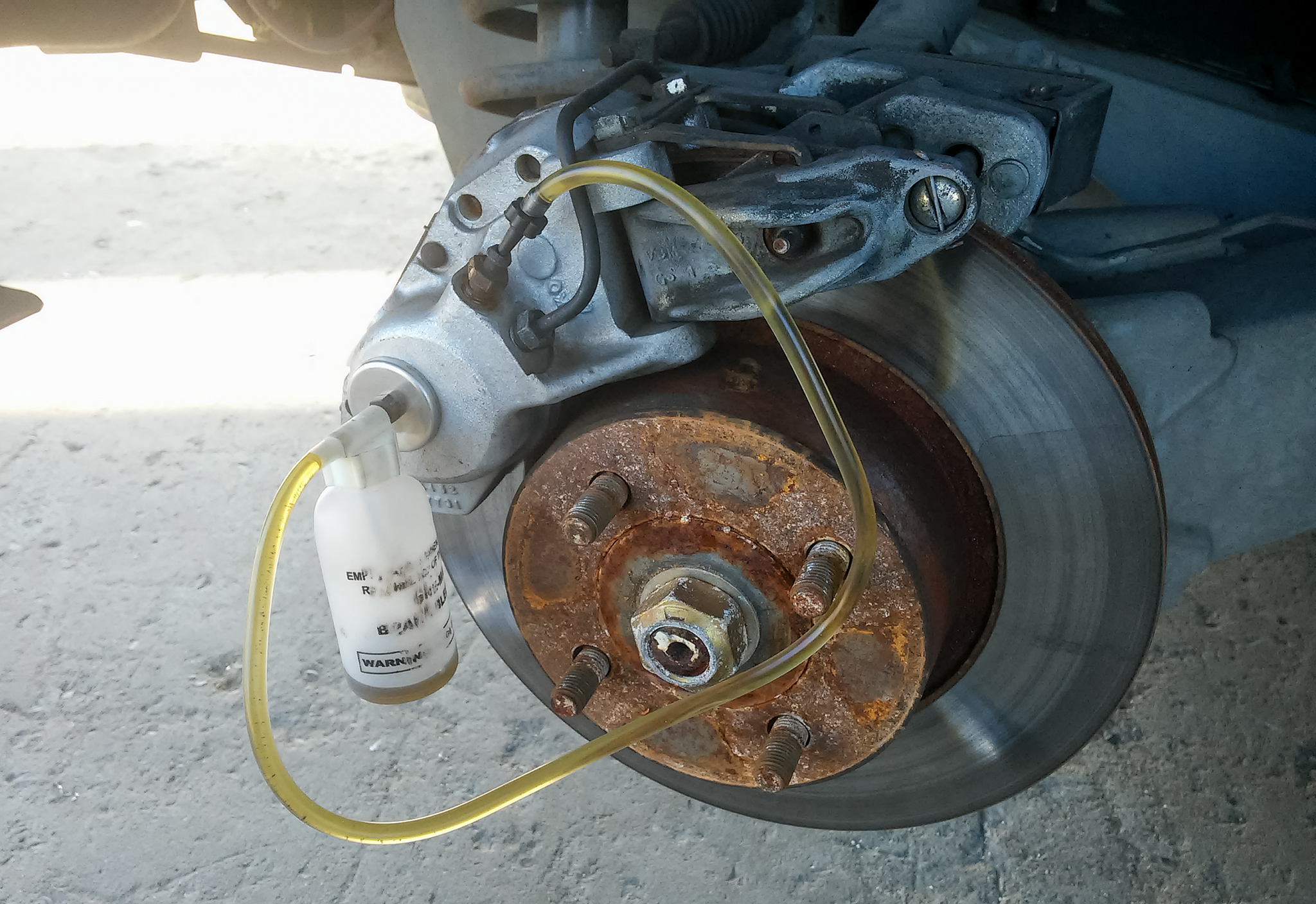
First set of fluid bled from my brake lines – super dark liquid in the bottle, tiny black flakes in the clear tube… This fluid change was definitely needed!
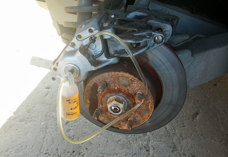
Part-way through the bleeding procedure. Remember to keep on topping up the reservoir as you bleed the system, you don’t want it to run low & pull air into the lines or else you have to start again
Bleeding finished, only clean fluid coming out now. You can see the liquid in the bottle is light coloured now. Time for the next wheel
After rinsing everywhere very thoroughly to make sure no corrosive brake fluid is left on anything, this job is done! This one’s not a very glamorous job, but ya gotta keep on top of the regular maintenance to keep a car running. 😉
Sometimes a problem can be caused by the tiniest thing. This was the case with my DeLorean’s horns – one of the two had stopped working so I was only hearing sound from the front left corner of my car.
Horns on a car are legally required to make a sound that resonates in two frequencies. Part of this is because some people have hearing difficulties in certain bands of the audio spectrum and it might just happen that they can’t hear your horn’s specific frequency, but also because if it was a single frequency there’s a chance that a car’s windows or body panels may attenuate that single specific frequency. But with two frequencies, the resonance between them creates harmonics that makes the alarm not only sound louder than it is, but because it’s now spread out over multiple frequencies there’s a much higher chance it will get through windows or body panels and it’s less likely someone will have hearing damage across all of its harmonics.
Some new cars have a single horn unit that operates on two frequencies, which is cheaper when made as a combined unit, but many older cars as well as large trucks just have two separate horns. Separate horns are simpler in their construction, they can usually be louder, and you can position them in different corners so the sound travels around your whole car better.
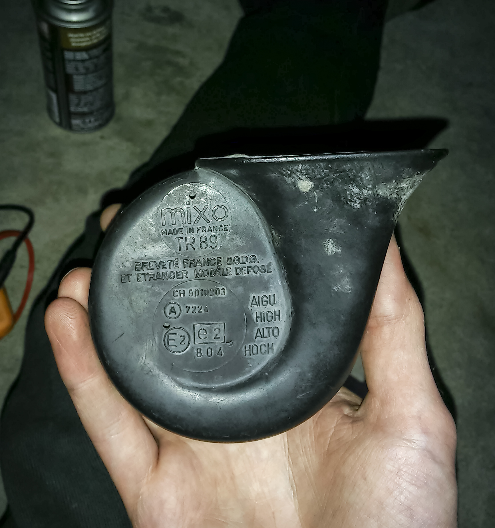
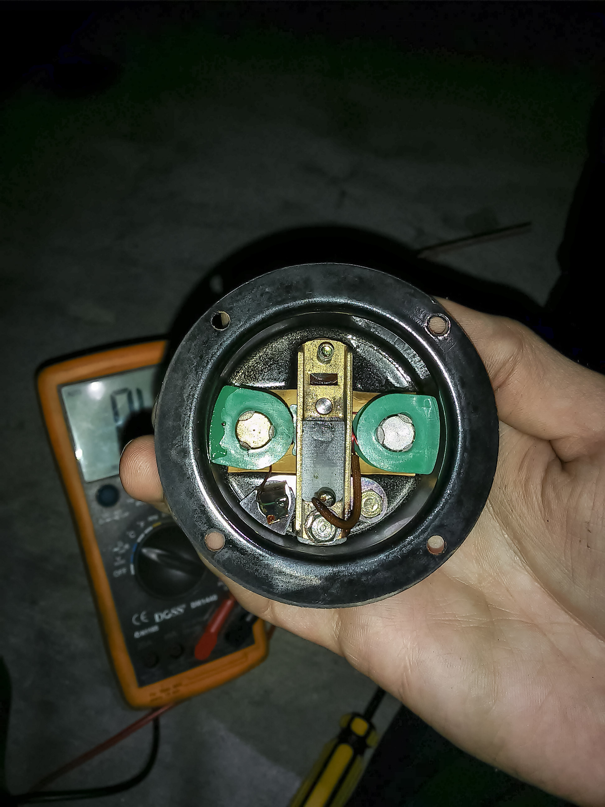
A DeLorean’s stock car horn – this is the “high” frequency one. This part is shared by dozens of other 60s/70s/80s/90s cars, notably Jaguars
Sure I could just buy another one since it’s only $20 for a New Old Stock one, but I wanted to see if it was repairable. So I opened it up to see what was inside and wouldn’t you believe it… A single piece of grit was resting between the contacts, preventing them contacting & completing the circuit. That’s it – a single speck of the wrong kind of dust in the wrong position and it stopped working!
Inside the horn – just some solenoids and a resonator attached to a metal diaphragm
I wiped down the horn’s internal components, reassembled it, and I also took the opportunity to clean the connectors of both of my horns – 35 years of corrosion does add a reasonable amount of electrical resistance, which makes for lower voltages & quieter horns. The end result – my horns now both work, they’re both louder than before, and I didn’t have to pay a cent to replace any parts. Score! 🙂
While trying once again to make my DeLorean’s voltage gauge more accurate, I decided to just jump to the very end – the actual gauge itself. At this point it’s the most likely component to be dodgy, but the wires leading up to it & the final connections to it could still haven’t been checked & cleaned, so I’ll tackle them too while I’m at it. One thing about DeLoreans, though – the easiest way to remove the dash’s instrument cluster is to just remove the entire binnacle… so that’s exactly what I did!
My DeLorean’s binnacle/dash instrument cluster, hooked up to a power supply & bench multimeter. Time to get serious!
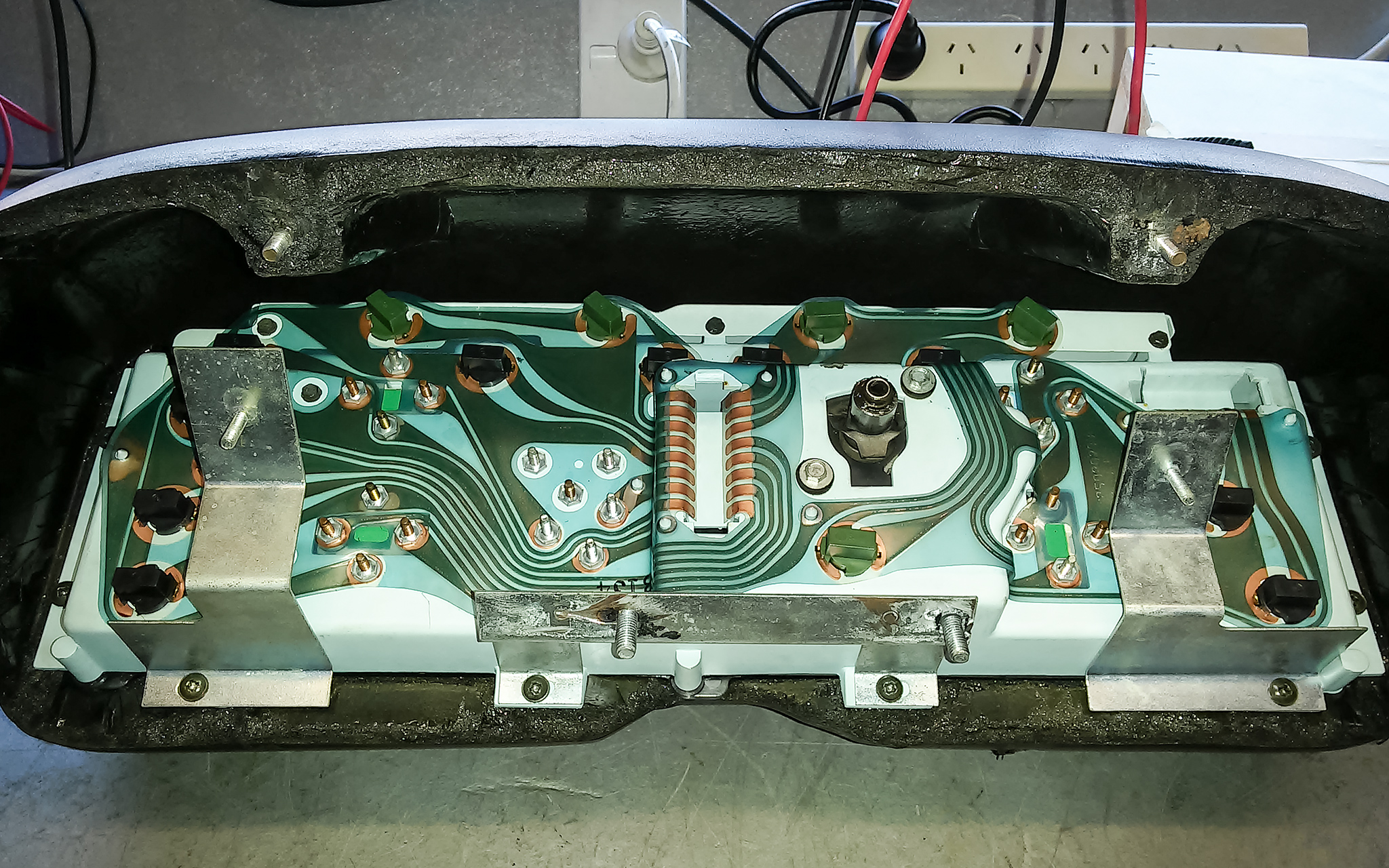
The dash instrument cluster on a DeLorean has a rather old-fashioned flexible plastic circuit board with mechanical connectors. This circuit board is incredibly fragile and should always be handled with great care, as the copper traces are thin & come loose from the plastic very easily. Thankfully mine’s in almost-perfect condition.
The rear of my DeLorean’s binnacle/dash instrument cluster – the small black/brown rectangular twist sockets hold all the light bulbs, one connector goes in the hole in middle, and the other connector goes in the hole in the top right
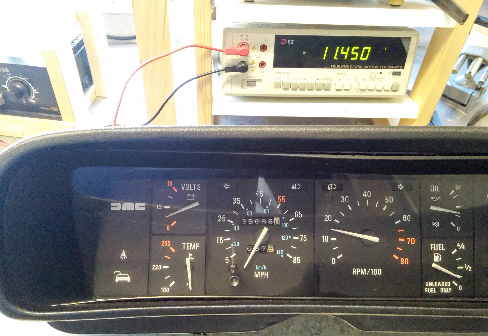
I attached the probes from the power supply straight to the threads of the voltage gauge – this bypasses absolutely everything and will give me the purest voltage reading possible. And just to be extra-sure, I didn’t rely on the voltage gauge of the power supply – I used one of the most accurate multimeters I have access to, an EZ Digital DM441B bench multimeter, which was also attached directly to the threads of the voltage gauge. Under these conditions this multimeter claims at least 0.1% accuracy to 4 digits, which should be good enough for around 0.01V. As expected, there was a slight voltage disagreement between the power supply and the multimeter, which is why I set it up this way because you should trust a dedicated multimeter’s reading far more than you trust a power supply.
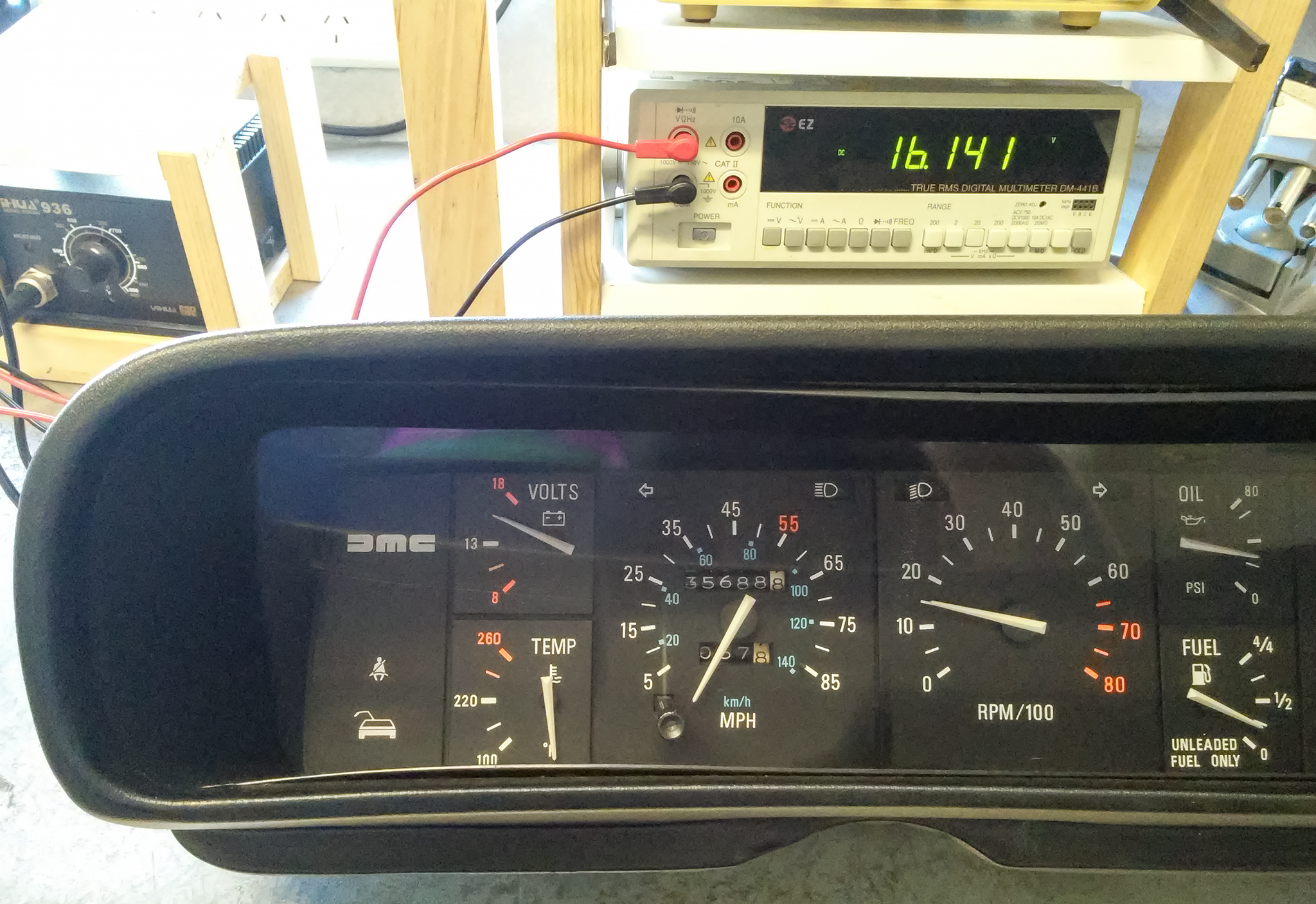
So I attached everything, turned it all on, set everything to the right levels, aaaaand…. It turns out my voltage meter itself is reading incorrectly! It’s incredibly non-linear too – the amount it’s off by varies up & down over the whole gauge, sometimes off by 0.2V and sometimes off by 4.5V, in a very random up-and-down polynomial curve not a simple offset or gradient. Something way too varied for me to simplify to a thing I could keep in the back of my head – in fact the only consistent thing is that it’s always under by a minimum of at least 0.2V. The good news though is that what the gauge currently displays as around “13.2V” is actually around 14V, so I now know that this is pretty much the sole reason why it’s reading low. I took a whole bunch of photos of the needle at different points for future reference – I won’t bore you by sharing all of them but here’s two showing how much it varies.
My DeLorean’s voltage gauge’s needle at the 10.5V marker when it actually has 11.45V going into it
My DeLorean’s voltage gauge needle at the 15.5V marker when it actually has 16.14V going into it
So, where to from here? Well since the error amount varies so much up & down over the gauge’s range, it isn’t really possible to disassemble & recalibrate this part – at least not for this kind of error. The best I could hope for would still give an incorrect reading 90% of the time. DMCh sells New Old Stock Voltage/Temperature Gauges, but there’s a good chance a replacement would also have calibration problems in a similar-but-different way, and I’m not sure this is worth $200AUD for that slight chance of improvement. So, I think I’ll just have to live with it.
While I was in there, I gave all the connections a solid clean with electrical contact cleaner & also repaired a bad contact in the Lambda counter socket. This boosted the voltage gauge another tiny bit, now to around 13.4V, which I know represents around 14.2V. I also made sure all the main connector pins are sticking out far enough, since one or two of them had started to retreat.
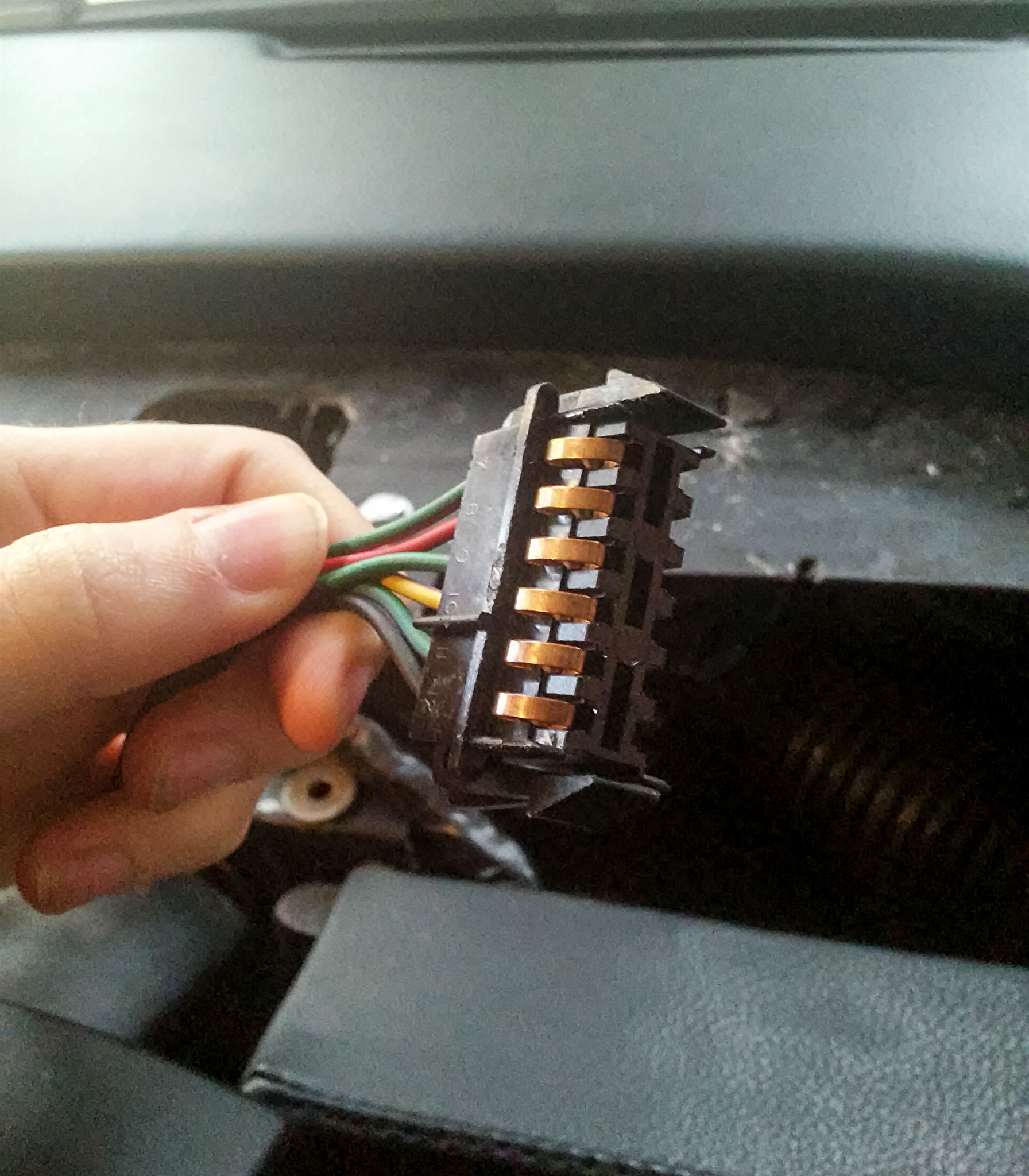
Speaking of, if anyone happens to know what these connectors are and where you can buy more… People are pretty sure they’re not DeLorean-specific, but as far as I’m aware no one in the DeLorean community has been able to 100% positively identify them over the past 40 years. In fact this is one of the few parts people have tried to 3D print to replace because it’s so unique/complicated and you really can’t make do without it. So there’s a challenge to you, dear readers! UPDATE: check the comments to this post, since I first wrote this years ago some helpful people have left some sources that look like they’ll do the trick!
The main central connector to the back of the DeLorean dash instrument cluster, before I fixed the two semi-dodgy pins
The secondary side connector to the back of the DeLorean dash instrument cluster. A source for these is listed in this post’s comments!!
Yet another weak point in the DeLorean’s electrical system is, well, almost all its grounds. In normal cars it’s common to ground everything directly to the metal body of the car, because it’s convenient and it’s everywhere. However because the DeLorean’s body is mostly non-conductive fibreglass, return wires have to be laid to act as grounds. And for reasons of cost cutting, many of these return ground wires are considered by most owners to be only barely adequate. In fact, aside from the cooling fans, almost everything electrical forwards of the rear engine bulkhead all goes back to just seven undersized wires, which all go through a single unreliable bulkhead bolt, which goes through a single cable back to the frame. That’s not a joke – both low-beam and high-beam front headlights, all the rear brake/indicator/park/reversing lights, the air conditioner blower fan, the fuel pump, the electrical compartment’s relays, ignition/idle ECU, the radio, it all shares the same grounding path & few wires. Including the dash and the voltage gauge on the dash – and it should be pretty obvious how this impacts the voltage gauge’s accuracy, along with all the other gauges in the instrument cluster too!
A diagram of most of the DeLorean’s grounding wire locations, courtesy Ron on DMCTalk – all these devices, only seven return wires, all connected to only one bulkhead bolt!
Continuing my recent electrical work, I wanted to see if I could make my dash’s voltage gauge a little more accurate. Also, a few of my other gauges are also a little inaccurate, all in ways that would be symptoms of receiving slightly lower voltage, and fixing the voltage issue should theoretically fix the calibration issues on all of them at the same time. I’ve been trying to improve the car’s voltage for a while now and it’s certainly better than it was, but I haven’t quite gotten it to where I want it yet. Even in the best-case scenario with a fully pre-charged battery in a running car that had been for a short drive with minimum electrical draw, the dash gauge would still only show apparently ~13.1V – almost a volt and a half lost from the 14.46V I measured from the battery. Given that I’ve cleaned the bulkhead bolt thoroughly & recently, I have the late Hervey’s upgraded double battery cable and I’ve minimised the power consumption in many other areas in my car through other mods/upgrades, I think it should be reading a little higher than it is.
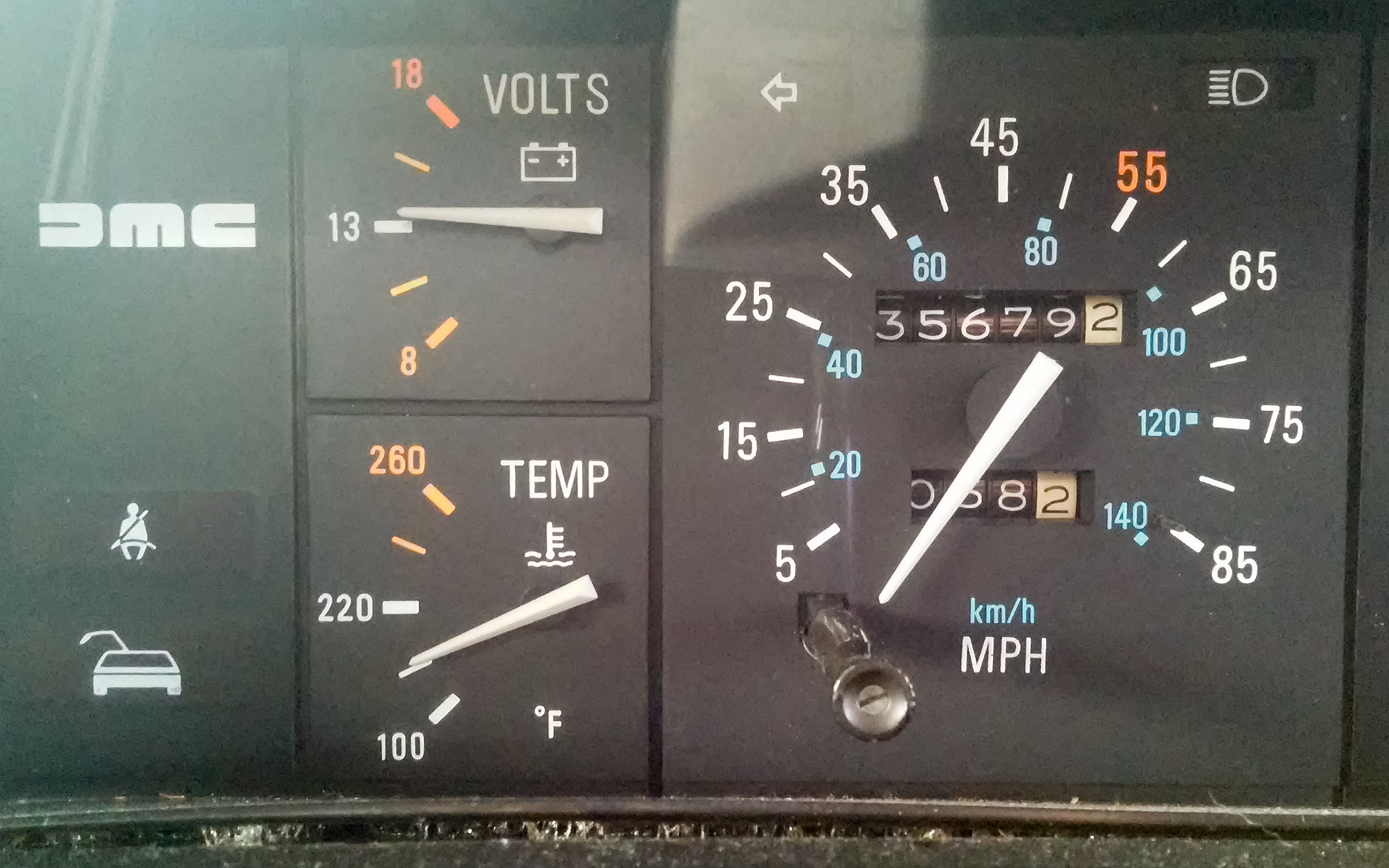
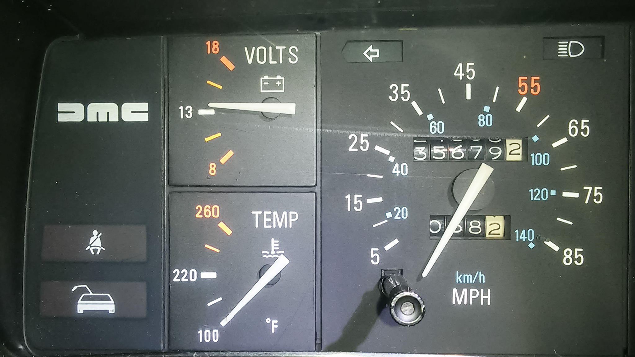
DeLorean dash voltage gauge – 13.1V according to here, but I measured 14.46V at the battery
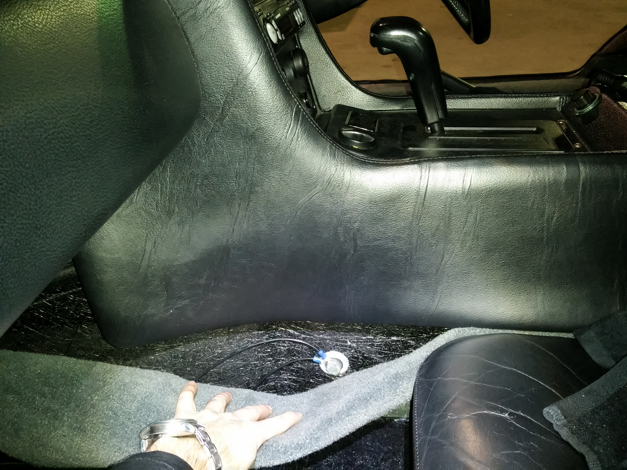
The dash shares its ground line with the fuel pump, which is a constant 7-8 Amp load. With the thin grounding wires in this car that’s certain to cause a voltage drop. Re-grounding the fuel pump is another common DeLorean mod, so that’s what I’m doing here today! The best place to do this with the least effort without bypassing any important safety features is right after the Inertia Switch, which is located in the foot-well of the driver’s seat (or, because some people like myself have a right-hand-drive DeLorean, it might be easier to say the foot-well on the left side of the car). Depending on the DeLorean’s manufacture date (and if it’s had all the recall notices applied), the Inertia Switch will either be located on the left fibreglass wall of the foot-well or it’ll be attached to the Service Interval Counter. The thicker black wire entering it is the ground wire. Because of my RHD conversion it’s a bit easier for me to gain access & photograph these areas than it is for the average DeLorean owner, so this post will be full of photos!
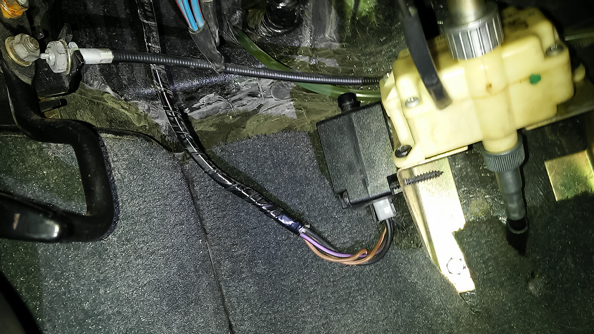
The Inertia Switch is the black box in the middle, which in my DeLorean was located to the left of the cream Service Interval Counter
The best place to re-ground this wire is to the frame bolt in the right of the foot-well. You shouldn’t even need to remove the centre console to access this bolt; just slide the carpet down (not by pulling out towards you, slide it down towards the floor so you don’t bend your vinyl-covered center console) and you should be able to reach it. This bolt goes right to the steel under-frame, which has a very thick cable connecting it straight to the battery, so it’s a good solid connection point.
Reference photo showing where the frame bolt is hidden behind the carpet – it’s just before where the Y-shape of the frame splits, between the front of the middle console and the gear stick
It’s a pretty simple process to splice in a new wire here. I used 15-Amp/16AWG wire because it was the thickest I had on hand and I considered the voltage drop over this small distance acceptable (it’s still well less than stock). I’m a big fan of over-doing connections in this car so the connectors were crimped, soldered and then heat-shrinked. I very very highly recommend you stay away from using a quick splice for such an important connection. It’s entirely possible to get away with doing only one wire on the half that’s connected to the Inertia Switch (and many would say that’s a better choice since it avoids adding a ground loop), but I opted to connect both halves of this wire to the new ground point, just to make sure my dash would always be properly grounded through redundant grounds.
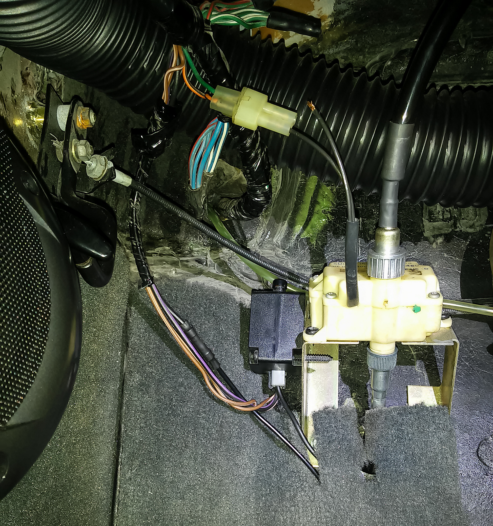
New wires spliced in place, while I show off just how much room I have in this area thanks to my car’s RHD conversion… And yes one of the wires from my service interval counter has come out of its plug – a future fix-it job for me!
On the other end of this new connection, the bolt & washer was cleaned with a wire brush and a thin layer of conductive carbon grease was applied. You can use 10.5mm (3/8″) ring terminals on this bolt, but I opted for 13mm (1/2″) ring terminals because they still fit perfectly with the washers etc and my 13mm rings had a larger contact area on them to make a better connection.
The two new connections are crimped on and ready to go
With that all done I pushed the carpet back in place, started the car, waited a few minutes for the alternator to recharge the battery to full, checked the dash, aaaaaaand….. Darnit. It’s reading around 13.2 Volts, a whole 0.1V higher than before, if that. It’s hardly moved!
All that work and the voltage gauge needle’s barely budged!
On a whim I checked the positive voltage at the electrically-closest point to the dash I could easily access, the Service Interval Counter. It measured 14.40V, which at the time was only ~0.114V voltage drop between that point & the battery. So clearly thems electrons are getting at least as far as the Service Interval Counter unhindered, and they should be able to leave unhindered through the new ground wires. I’ve checked/replaced/upgraded around 90% of this circuit, so the problem has to be somewhere in that last 10% containing the voltage gauge itself, the binnacle and the wires directly to and from it.
This hasn’t been waste of time, though. My fuel pump now has a much better electrical connection, and it’s now running very audibly quieter due to its higher, more normal operating voltage. So quiet in fact that I can now barely hear it, which is also due in part to the new Solid State RPM Relay and recently cleaning up the connections in the electrical compartment. This means it should last longer, and my engine should receive a higher fuel pressure under heavy load, giving it a little more oomf. But better reliability is the main benefit, and in this car that’s always a good thing. It also means that since this change did little to improve the dash voltage, the rest of my grounds are already working perfectly with no corrosion slowing them down, so that’s also good news. I’m almost there to solving this problem!
One of many known “weak points” in the DeLorean is the RPM relay. You might think that with a name like that it would have something to do with the tachometer or the engine’s revolutions per minute – but no, that’d make too much sense for this car. 😉 This is a pretty custom relay with basically only one main a crossover to a Volvo unit that’s no longer manufactured (or available). Thankfully there’s a plentiful supply of spare ones made by DMC back in the day, and this old stockpile is still the most reliable New-Old-Stock stockpile available (in fact some Volvo owners order DMC ones). But that doesn’t mean it’s absolutely perfect.
So what does it actually do? Basically, this relay is responsible for priming the fuel pressure when the car is being started, enabling the fuel pump when the engine is running, as well as providing power to the warm-up regulator when necessary. The problem is, this means you have a relay coil that is constantly energised the entire time the car is running – and if connectivity misses for even just a moment then you’ll lose fuel pressure and the engine will sputter at best (and die on you at worst). All relays have a habit of dying with time, particularly ones fitted inside DeLoreans. In particular, the fuel priming functionality is normally the first functionality to go as the electrolytic capacitor dies out over time, and if that happens the car simply won’t start. This relay fails often enough, is important enough, and is unique enough that many owners actually recommend you keep a spare in the glove box. Fortunately, someone other than me saw this problem and went about rectifying it with a modern replacement – Enter Dave McKeen/Bitsyncmaster’s Solid State RPM Relay!
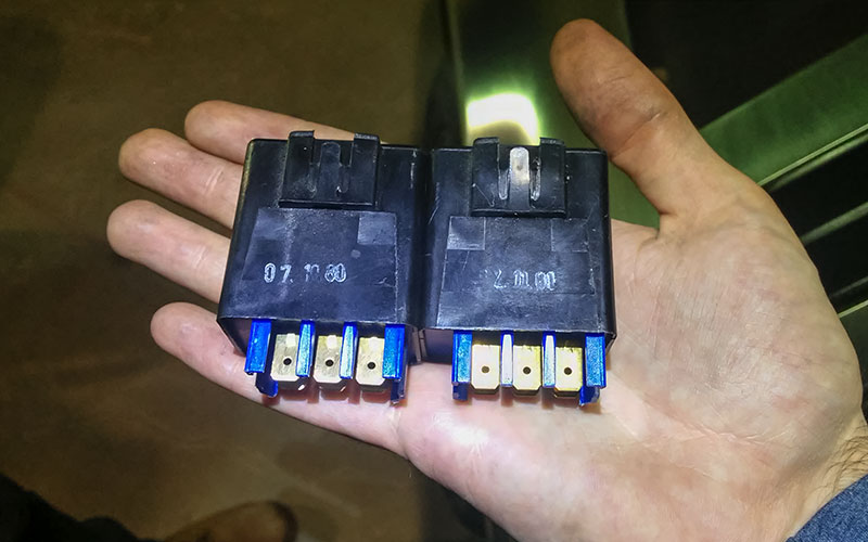
On the outside, these two units look completely identical…
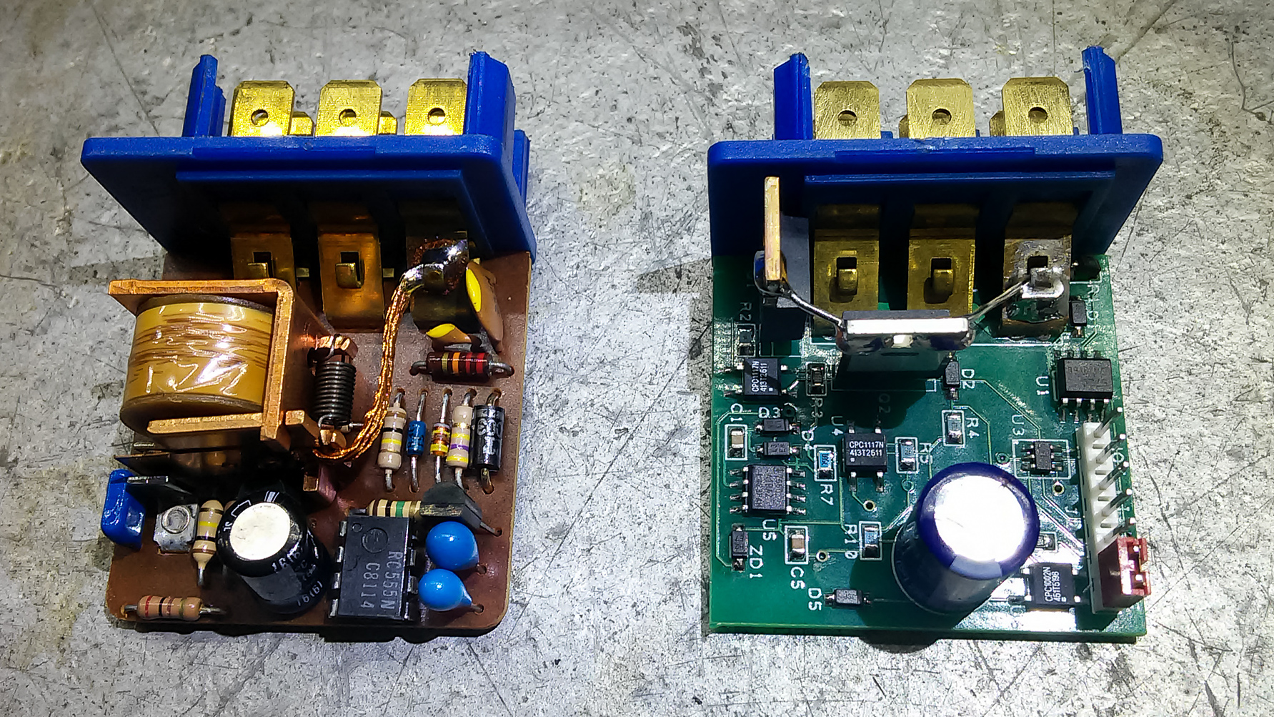
…But on the inside, it’s clear that these are nothing alike!
His replacement is amazeballs. It’s all solid-state so it’s far more reliable, it consumes a fraction of the power of the old one reducing both the load on the alternator and the heat generated inside the electronics compartment, it guarantees fuel auto-priming when starting the car every time & for the correct amount of time, it runs the fuel pump for half a second after turning off the car to boost your resting fuel pressure to help prevent hot start issues, and being a digital, microcontroller-based device it’s far better at handling dodgy signals from poor connections & old, corroded wires. What’s more, it comes with an optional feature you can enable using the jumper – the “hot fix” function which runs the fuel pump for half a second every hour for 3 hours after you shut down the engine, which helps the car start quickly again when the engine is hot if your car has trouble maintaining its resting fuel pressure. I don’t have that problem so I’ve left it disabled.
This is one of those “set and forget” upgrades, so there’s not much I can say about actually installing it. It’s in there now, I noticed my car now starts a little quicker because the fuel pressure is always perfect when starting the car, and there’s no heat in that area of the electronics compartment any more when I’ve been driving the car for a while. Hopefully I’ll never have to worry with this ever again – and I can enjoy never getting stranded because my RPM relay failed! 🙂
You can buy an upgraded solid-state DeLorean RPM relay by emailing Dave McKeen/Bitsyncmaster; his details along with his other upgrades are on his website at dm-eng.weebly.com (but you may need to disable your Ad blocker to see his email address, it gets blocked by some “social” filters).
I received a bunch of positive feedback about documenting repairing my DeLorean’s shorted electrical compartment, particularly quite a few people who were curious about what kind of work it takes to maintain a DeLorean. So I’m gonna try posting details of all my constant fix-it jobs/upgrades on here. Let’s see how this goes!
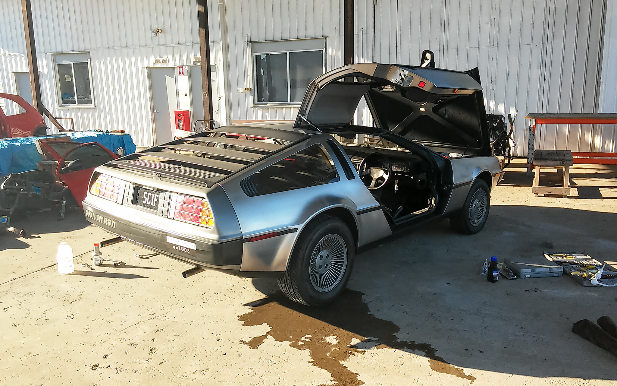
My DeLorean on display at an event inside Brisbane City Hall
The whole reason I was fiddling in the electrical compartment in the first place was to work out why my cooling fans weren’t turning on. Once the car was running again, I vowed to make sure I would never have that problem any more. In its original condition the car had an indicator light on the dash that lit up when the cooling fans weren’t working, however the way this circuit worked was SO fraught with problems that the circuit itself tended to die way more frequently than the fans did, and when the circuit died it also caused the fans to fail. The standard workaround for the last 30-something years was to just jumper past the fan fail circuit. Yes this was something people were bypassing even when the car was brand new, it was so problematic. When I went through my electrical compartment I noticed my (new when I bought the car, I might add) bypass wire had turned brown from excess heat and needed replacing, so I decided it was time to fix this in a way that not only gave me more reliability with my cooling fans but re-enabled my cooling fan fail warning light again.
My DeLorean’s cooling fan jumper bypass wire – browned from overheating, it needs replacing anyway
There’s a few options here – the main ones are to either replace it with another new jumper wire and forget about the light, or go back to the original configuration that’s fraught with troubles. Thankfully one of the people in the DeLorean community, Dave McKeen aka Bitsyncmaster, offers a much better solution. He’s put together a dual-pcb solid-state replacement with fuses on top. This replacement gives dual wiring with individual fuses per fan, which will to try and keep at least one fan operating if the other fails. And if one (or both) fans fail, the cooling fan fail light on the dash doesn’t just turn on – it flashes, which grabs your attention pretty well. What’s more, it also offers current sensing capabilities so if the current between the two fans falls outside a certain tolerance (user-configurable but by default it’s 20%), indicating that one of your fans either has a still-there-but-poor connection or is close to dying, the cooling fan light will flash too. The flashing pattern is different depending on the error code so by just looking at the warning light’s pattern, you can quickly tell that not only is something wrong with your cooling fans, but which one has the fault, and in what way it’s failed. And for some icing on the cake, the whole component is encased in watertight, airtight resin so it won’t corrode in the electronics compartment. Pretty swanky! I opted for the version with physical fuses instead of the one with resettable electronic fuses because, while I don’t doubt his engineering skills, the physical fuse version has a lot more use by other DeLorean owners.
The new upgraded fused fan fail relay. Apologies for the dirty hand; I still had liquid electrical tape on me from repairing wires!
I installed it then tested different failure modes by removing the fuses to simulate failed fans. The warning light blinked in the right pattern, indicating the circuit worked perfectly. Huzzah! 😀
Now for the next area in the cooling fan circuit that I thought could do with some love – the main enabling relay! This is just a standard automotive relay that is used to turn the fans on or off, but it can still be improved. The cooling fans turn on under two circumstances – the first is when the coolant temperature reaches a certain point – and as you can imagine, this can result in a little bit of fan cycling when things are right at the cutoff limit for the thermal switch. This means a large load is switched on and off repeatedly, which causes lots of spikes & sags in the car’s electrical system. The second time it turns on is when you turn on the air-conditioning of the car – at which point the air-conditioner’s compressor kicks on (another sudden huge momentary electrical load & corresponding spike), the engine’s RPM momentarily drops from the extra resistance of the compressor which means the alternator temporarily sags in its output, and the cooling fans both turn on (another huge sag of voltage plus enabling some of the largest constant loads in the whole car).
DM-eng offers a replacement smart Solid State Fan Relay as a drop-in replacement in the relay socket. Basically this is a solid state relay (which means is uses less power and can be more reliable), that delays turning on the fans by one second after the enabling signal is received (to allow the air conditioning compressor clutch’s sag and the engine’s RPM drop to settle itself), and then also guarantees the fans will run for a minimum of 20 seconds (to help eliminate constant on/off cycling). Again it’s encased in watertight, airtight resin for longevity and you can see an example of its construction on his website.
Super boring looking, but a super useful upgrade
Fitting this upgrade was as simple as doing a relay swap. Its operation was tested with an oscilloscope, both to check the delay function and its impact on the car’s electrical systems. The delaying actions worked exactly as they should, and there was a marked improvement in voltage smoothness when the AC was enabled or disabled thanks to its staggered approach. I’ll call this one a win! 🙂
You can buy both of these relay upgrades by getting in contact with Dave McKeen, also known as BitSyncMaster, via his website.
Now that my cooling fans seem to be working perfectly, it’s time for me to move on to other electrical areas…
I live in a house that has the occasional indoor dampness & mould problem after heavy rain, so years ago I purchased a sizeable dehumidifier. The way it works is similar to a standard air-conditioner except the hot and cold sides are right next to each other, to make it far more efficient and much better at condensing moisture out of the air than just running the air conditioner.
There’s one downside to my dehumidifier though – its dust filter is best described as a hair filter, because it’s just a grid of plastic that will do nothing to purify the air that passes through it. So I thought I could improve this by turning it into a proper air filter too. It’s also a bit noisier than I’d like, so finding a way to quieten it a little would be amazing.
What’s more, right now in 2016 if you’ve ever looked up the prices of dedicated air filters to remove dust/pollen/allergens/smoke/smells, they’re super expensive for what they are. Box fans are cheap, filter material is cheap, but somehow if you add the two together into a dedicated appliance you end up spending nearly a thousand dollars to get an acceptable-micron-filtration one at 2016 prices. That’s just bonkers to me! I really thought there would be cheap Chinese knockoffs to filter the poor air in China, but I couldn’t find any that had the specs to actually work properly, only dodgy ones that wouldn’t filter everything. So, it’s time to get hacking!
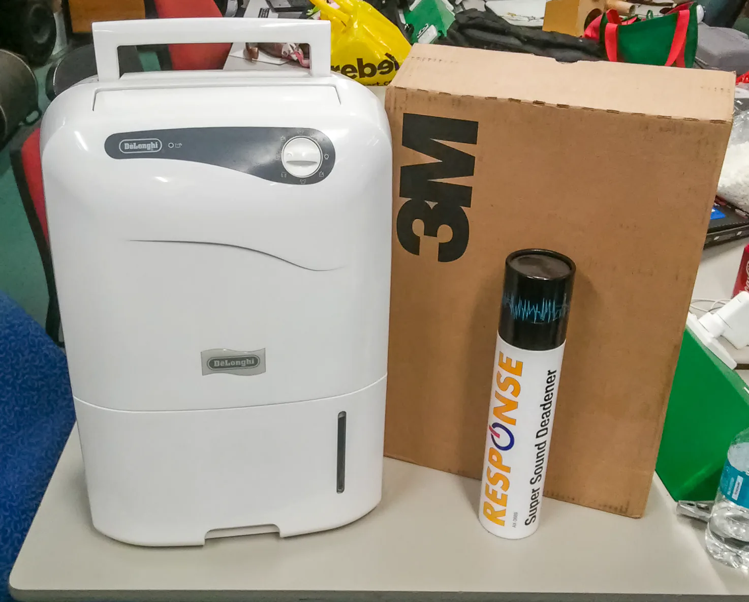
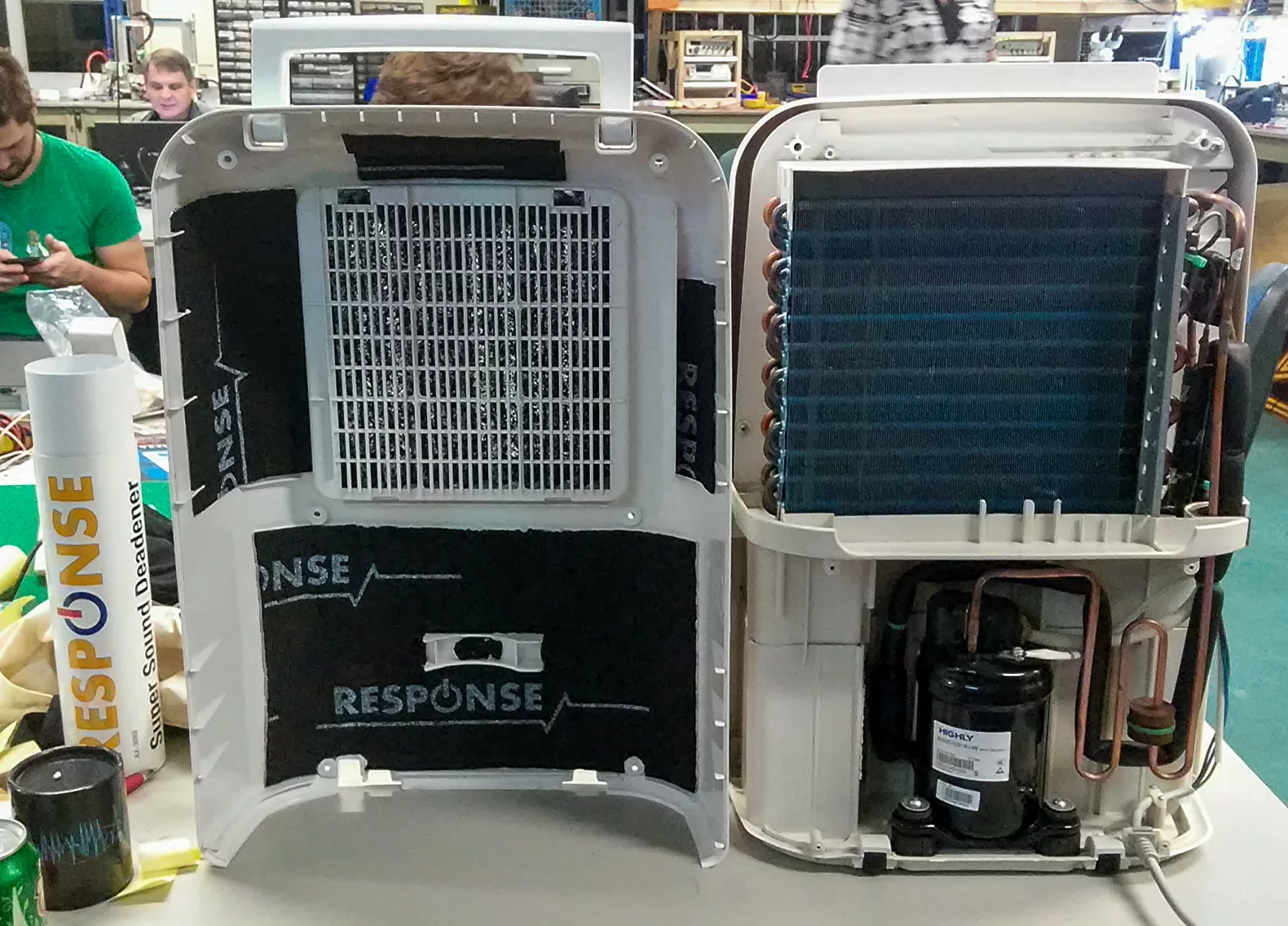
The dehumidifier in question, along with some supplies I’ll be using
In my research of filtration materials, I found that the cheapest source of stuff (including shipping) in 2016 that will go down to a fine enough micron is the filter refill packs sold for furnaces in America. Comparing the market with tech specs galore, the final material I decided upon was 3M’s Filtrete MPR1200 1. This isn’t the highest level particulate filter around but it’s efficiency in the 0.3-1.0 micron range is 85% (meaning most bacteria will be caught let alone smoke etc), its pressure drop at the standard weave packing is only 0.24 (meaning it won’t overwork the motor on my dehumidifier), it has a metal mesh built in so it will retain its shape without sagging when left vertical, and most importantly it has the highest activated carbon content of any filter on the market (meaning it will remove smells that are entirely gaseous in their nature). And check out that price for a 4-pack of big sheets of the stuff – it’s also pretty darned cheap for what it is, and a 4-pack will do me for many years with regular changes.
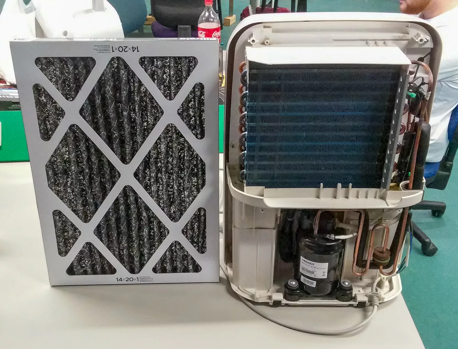
Inside the dehumidifier showing the compressor at the bottom and the evaporator (cold side) mounted right in front of the condenser (hot side), with the filter material on the left. Mmm, carbon goodness.
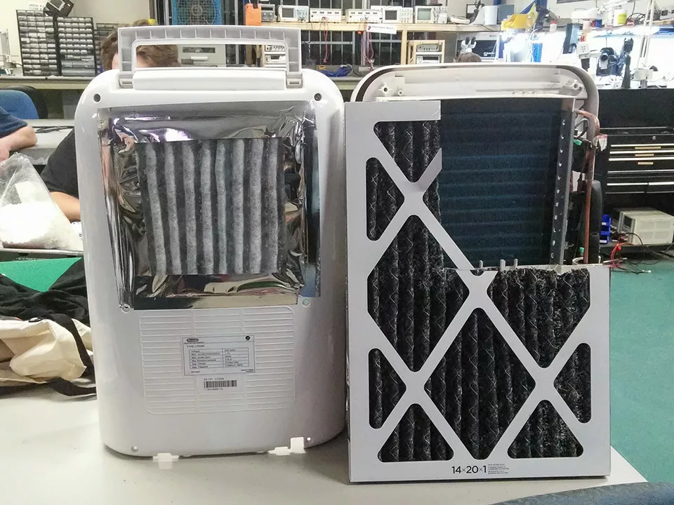
Swapping the filter material was as easy as removing the old plastic grill “filter”, cutting the filter material to size, and affixing it in place. For temporary testing I’m using some silver ducting tape I had left over, because I prefer its sticky properties over normal duct tape but also because it looks slightly less hacky than the usual grey stuff everyone uses. If you’re using the same filter material I am, pay attention to the mounting direction for airflow – the air needs to be filtered via the white side first, then hit the black carbon-filled side second! The filter material I used was also compressed a little more than it came so it had more pleats, to reduce the pressure drop even more.
All applied to its back side, with plenty of leftover filter material to spare
Now for the next step – quietening the machine!
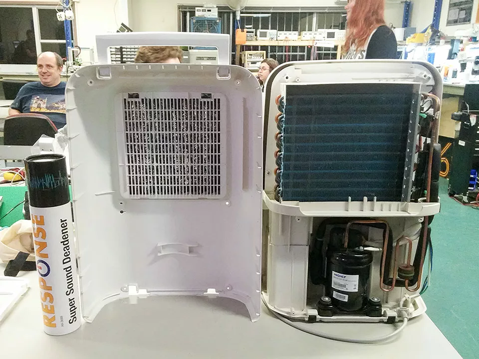
The view from inside before any soundproofing material was applied
Testing with my ears confirmed that this unit is slightly quieter with the case off than on, which sounds a little weird and unexpected, if you’ll pardon the pun. Testing with my hand showed quite clearly the cause of a lot of the device’s noise was the large back plastic case picking up vibrations from the compressor and reverberating like a sub-woofer. The easiest way to fix vibrations transmitted like this is to add some mass to the panels, preferably slightly decoupled from the final plastic layer. But why not go all out with some sound absorbing foam too! I had some leftover butyl/foam sound deadening material 2 from another project, so I applied it to the interior of the case.
I’m (not) picking up good vibrations, it’s (not) giving me the excitations
With that all done, it was time to put the screws back in, test it and… holy heck it’s now much quieter! Still audible, but nowhere near as annoying. I tested the filter’s effectiveness by lighting some incense in a small sealed room, stinking the whole room up, then turning on the dehumidifier. The incense smell was undetectable after fifteen minutes, so I know that works well too!
Finished machine from the front – undetectable from stock
I now have a many-hundreds-of-dollars-equivalent air filter as well as a dehumidifier. Woot!
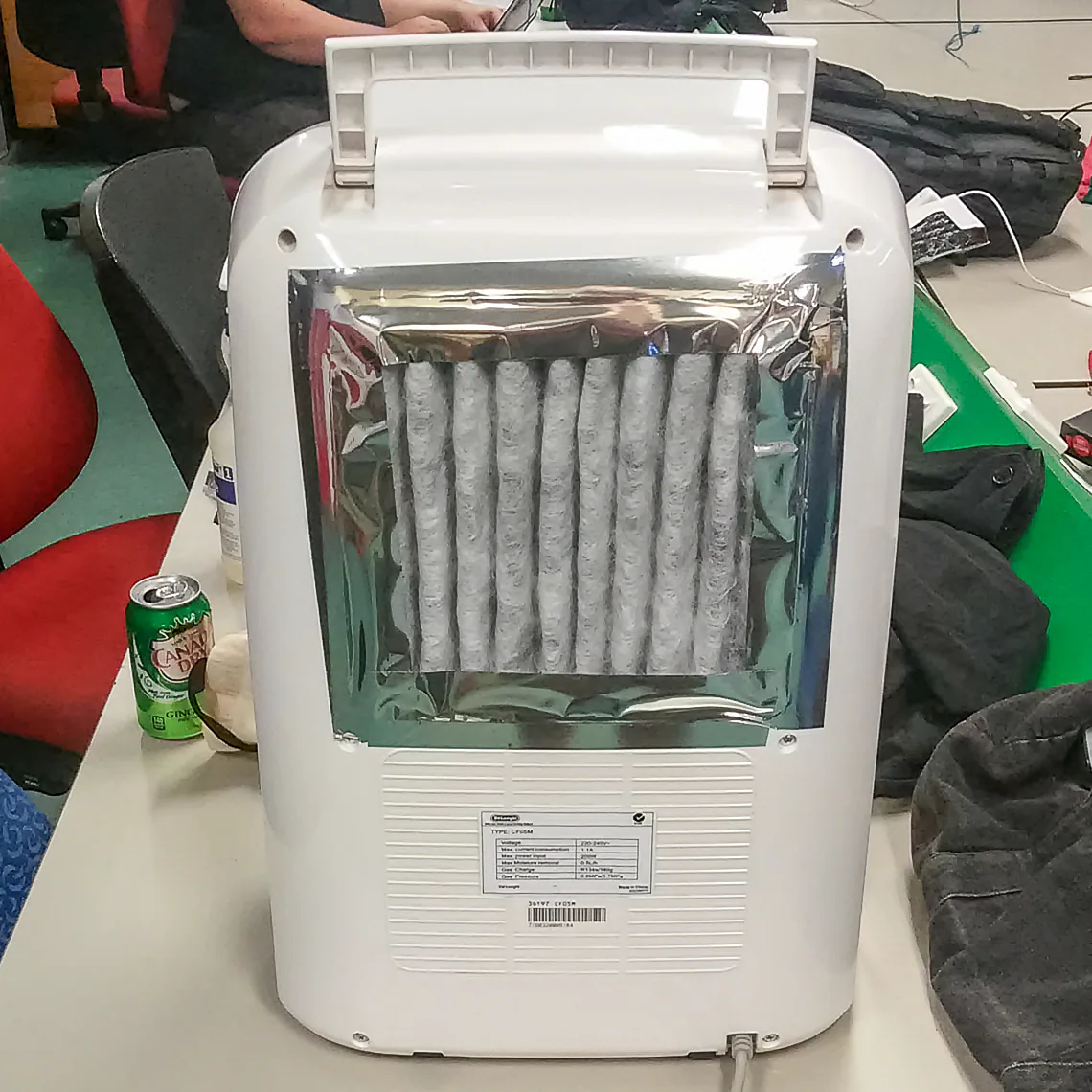
Finished machine from the rear – a little hacky looking, but function over form, amirite?
I’m Mike Ando, a time-travelling mad scientist. DeLorean driver. Satellite owner. Inventor. Potato connoisseur. Once on Beauty & the Geek Australia, now a Professional Geek.